
Basic Documentation
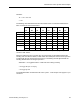
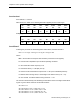
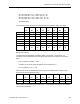
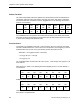
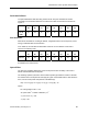
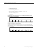
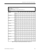
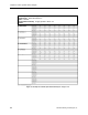
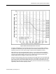
Table Of Contents
- About this Application Guide
- Chapter 1–Introduction
- Chapter 2–Physics of Sound
- Chapter 3–HVAC Sound Sources
- Chapter 4–HVAC Sound Attenuation
- Introduction to HVAC Sound Attenuation
- Plenums
- Duct Attenuation
- Duct Takeoffs and Divisions
- Duct Silencers
- End Reflection
- Environment Adjustment Factor
- Space Effect
- Radiated Sound Attenuation
- Chapter 5–HVAC System Sound Analysis
- Chapter 6–Minimizing HVAC Sound
- Appendix
- Glossary
- Index

Introduction to HVAC System Sound Analysis
St = 60 x 1000 Hz x 1.0 ft ÷ 1,528 = 39.3, K = -53
St = 60 x 2,000 Hz x 1.0 ft ÷ 1,528 = 78.5, K = -63
St = 60 x 4,000 Hz x 1.0 ft ÷ 1,528 = 157.1, K = -74
St = 60 x 8,000 Hz x 1.0 ft ÷ 1,528 = 314.1, K = -95*
*Estimated Value
The chart below sums up the factors comprising the ELw values for each octave band.
63 125 250 500 1,000 2,000 4,000 8,000
Hz Hz Hz Hz Hz Hz Hz Hz
K -21 -28 -35 -44 -53 -63 -74 -95
10 Log F 18 21 24 27 30 33 36 39
50 Log U 159 159 159 159 159 159 159 159
10 Log S -1 -1 -1 -1 -1 -1 -1 -1
10 Log D 0 0 0 0 0 0 0 0
JC -107 -107 -107 -107 -107 -107 -107 -107
JLw 48.0 44.0 40.0 34.0 28.0 21.0 13.0 0
dB dB dB dB dB dB dB dB
These values are now entered into the HVAC system - sound analysis form (Figure 17) as
Elbow J GNL entries.
To approximate the attenuation provided by either a rectangular or round elbow, it is
necessary to first calculate the Frequency Width (FW) factor for the elbow at each octave
band.
FW = (Frequency x Width) ÷ 1,000
Frequency is the octave band Hz. Width is the duct width (12 in.)
FW = (Frequency x 12) ÷ 1,000
When the FW values are determined, Figure 16 gives the dB attenuation at each octave
band from the ROUND ELBOWS curve.
63 125 250 500 1,000 2,000 4,000 8,000
Hz Hz Hz Hz Hz Hz Hz Hz
FW
0.76 1.5 3.0 6.0 12.0 24.0 48.0 96.0
ATTN:
0.2 dB 0.5 dB 1.8 dB 2.8 dB 3.3 dB 3.3 dB 3.0 dB 2.7 dB
These values are entered into the HVAC system - sound analysis form (Figure 17) as Elbow
J ATTENUATION entries.
Siemens Building Technologies, Inc. 81