
Basic Documentation
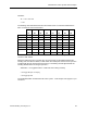
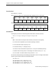
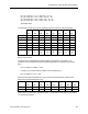
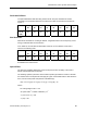
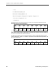
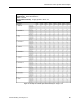
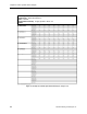
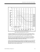
Table Of Contents
- About this Application Guide
- Chapter 1–Introduction
- Chapter 2–Physics of Sound
- Chapter 3–HVAC Sound Sources
- Chapter 4–HVAC Sound Attenuation
- Introduction to HVAC Sound Attenuation
- Plenums
- Duct Attenuation
- Duct Takeoffs and Divisions
- Duct Silencers
- End Reflection
- Environment Adjustment Factor
- Space Effect
- Radiated Sound Attenuation
- Chapter 5–HVAC System Sound Analysis
- Chapter 6–Minimizing HVAC Sound
- Appendix
- Glossary
- Index

Chapter 5–HVAC System Sound Analysis
Reheat Terminal
The reheat terminal GNL values are obtained from the manufacturer and are restated in the
chart below. (Note also that in this example, the short duct section after elbow J and before
the Reheat Terminal is considered to have a negligible effect on the discharge sound and is
therefore not evaluated.)
63 125 250 500 1,000 2,000 4,000 8,000
Hz Hz Hz Hz Hz Hz Hz Hz
Terminal
GNL*
73
dB
70
dB
66
dB
62
dB
56
dB
54
dB
49
dB
44
dB
* Discharge Noise Data Based Upon Reverberant Test.
The COMBINATION sound pressure level values that result due to the reheat terminal GNL
discharge sound and the preceding sound pressure level are derived with reference to Table
3, which covers adding sound pressure levels.
Duct Sections L
Two flexible 12-inch diameter ducts with 1-inch thick lining. Since the outlet from the reheat
terminal is divided between two 12-inch ducts, the sound power in at the beginning of each is
divided between the two duct runs by the following junction attenuation formula:
Attenuation = 10 Log [Branch Area ÷ Total Area]
= 10 Log [0.79 sq ft ÷ 1.58 sq ft]
= 10 Log [0.5] = 3.0
The 3.0 dB attenuation is entered into the HVAC system - sound analysis form (Figure 17) as
Duct Division L.
With reference to Table 17, the following attenuation applies per foot of 12-inch diameter, 1-
inch lined duct:
63 125 250 500 1,000 2,000 4,000 8,000
Hz Hz Hz Hz Hz Hz Hz Hz
0.23
dB
0.46
dB
0.81
dB
1.45
dB
2.18
dB
1.91
dB
1.48
dB
1.05
dB
Multiplying these values by the 10 feet yields the following attenuation in each octave band:
63 125 250 500 1,000 2,000 4,000 8,000
Hz Hz Hz Hz Hz Hz Hz Hz
2.3
dB
4.6
dB
8.1
dB
14.5
dB
21.8
dB
19.1
dB
14.8
dB
10.5
dB
These values are now entered into the HVAC system - sound analysis form (Figure 17) as
Duct Section L ATTENUATION.
82 Siemens Building Technologies, Inc.