
Basic Documentation
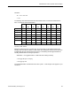
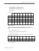
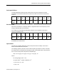
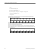
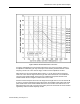
Table Of Contents
- About this Application Guide
- Chapter 1–Introduction
- Chapter 2–Physics of Sound
- Chapter 3–HVAC Sound Sources
- Chapter 4–HVAC Sound Attenuation
- Introduction to HVAC Sound Attenuation
- Plenums
- Duct Attenuation
- Duct Takeoffs and Divisions
- Duct Silencers
- End Reflection
- Environment Adjustment Factor
- Space Effect
- Radiated Sound Attenuation
- Chapter 5–HVAC System Sound Analysis
- Chapter 6–Minimizing HVAC Sound
- Appendix
- Glossary
- Index

Chapter 5–HVAC System Sound Analysis
= 1.44
f = octave band frequency Hz.
N = number of ceiling diffusers = 2.
RLp = 27.6 Log (10) + 5 Log (1.4) + 3 Log (Hz) -1.3 Log (2) – 30
= 27.6 +0.7+ 3 Log (Hz) -0.4 – 30
= 3 log (Hz) -2.1
Substituting each octave band frequency in the Hz term will yield the following room dB
attenuation values at each octave band:
63 125 250 500 1,000 2,000 4,000 8,000
Hz Hz Hz Hz Hz Hz Hz Hz
3.3
dB
4.2
dB
5.1
dB
6.0
dB
6.9
dB
7.8
dB
8.7
dB
9.6
dB
The attenuation values determined for the room are then subtracted from the sound power
level values that are present at the diffusers to yield the sound pressure level five feet above
the floor in the vicinity of the respective diffuser.
The last row of entries on the second part of Figure 17 show the dB sound pressure level
values calculated for Room 101. These are reproduced in the chart below and plotted on the
RC curve of Figure 18.
63 125 250 500 1,000 2,000 4,000 8,000
Hz Hz Hz Hz Hz Hz Hz Hz
54.8
dB
55.1
dB
54.9
dB
44.8
dB
34.0
dB
31.9
dB
31.0
dB
29.9
dB
84 Siemens Building Technologies, Inc.