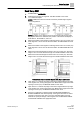
Fume Hood Sash Open Area Module (SOAM) Application 2951: 4 Independent Vertical Sashes, Bench Mounted Configuration Start-up Procedures Building Technologies A6V10801591 07.06.
Table of Contents Before You Begin ..................................................................................................3 Verifying Power .........................................................................................................3 Installing USB Driver .................................................................................................3 Verifying Slave Mode Application ..............................................................................
Before You Begin Verifying Power Before You Begin WARNING A fume hood is a safety device. Anyone attempting to start up a Fume Hood Controller and its related equipment must have completed Operations Training. WARNING DO NOT connect to the USB port of the SOAM while the fume hood is in operation. At the job site, locate the major control system and the mechanical and electrical drawings. This should include any components working in conjunction with the Sash Open Area Module (SOAM).
Before You Begin Setting Controller Address Setting Controller Address 1. If using the sensor bus to communicate the face area: Verify CTLR ADDRESS is correct (default is 51 and does not need to be changed). Setting the Application 1. Select the desired application.
Before You Begin Fume Hood Specific Sash Setup and Calibration Sash Setup 2951 1. Set REPORT to OVERVIEW. 2. Determine the number of segments. Set SEG COUNT to this value. 1 to 4 will be accepted. NOTE: A DXR Fume Hood Controller can directly handle single segment hood configurations. NOTE: Numbers on the sashes show how the sash should be wired. After the physical sashes are calibrated, the position of the sashes will display in POS SASH 1, POS SASH 2, and so on. 3.
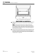
Before You Begin Fume Hood Specific Sash Setup and Calibration Example Vertical Sash Fume Hood with Fixed Area. 10. Measure the fixed area of the fume hood in square feet (m2). Any fume hood leakage must be accounted for in this measurement. Set FIXED AREA to this value. NOTE: The fixed area of the fume hood is an area that remains open regardless of sash position or movement.
Before You Begin Fume Hood Specific Sash Setup and Calibration Sash Calibration NOTE: The full travel of the sash must be used during calibration. 1. Set CAL SASH NUM to 1. 2. Verify CAL SASH LOC is set to MIN. 3. Slide vertical sash 1 to the closed position. Measure the distance from the bottom of vertical sash 1 to the bottom of the sash opening in inches (cm). Set CAL SASH POS to this value. When the SOAM accepts the reading, CAL SASH POS will revert back to 257 and CAL SASH LOC will switch to MAX.
Before You Begin Setting External Face Area Input Setting External Face Area Input Skip this section if you are only using one SOAM, leave values at default. AI can be set up as an input for external face area. 1. Set MAX EXT AREA to the area corresponding to 10 volts from the input signal source. The next step allows the minimum voltage to bet set to a value other than 1 (default). The minimum voltage is represented when the face area is equal to 0. 2.
Before You Begin Flashing Controller Firmware Flashing Controller Firmware WCIS Procedure 1. Connect to the USB port of the SOAM. 2. From the Device menu, select Load TEC Firmware. The Load TEC Firmware dialog box displays. 3. Click the Browse button. 4. Browse to the folder where the new firmware is saved. 5. Double-click the firmware file and then click Load. 9 | 10 A6V10801591 Siemens Industry, Inc. Restricted 07.06.
Issued by Siemens Industry, Inc. Building Technologies Division 1000 Deerfield Pkwy Buffalo Grove IL 60089 +1 847-215-1000 © Siemens Industry, Inc., 2016 Technical specifications and availability subject to change without notice. Document ID: A6V10801591 Edition: 07.06.