
Installation Instructions

Document No. 546-00011
Installation Instructions
Rev. 2, October, 1999
Page 2 of 5
Siemens Building Technologies, Inc.
Electronic Actuation
Wiring the AO-E Module and differential pressure
transmitter to the Fume Hood Controller.
FHET Installation
Installation of the FHET in the exhaust duct or on
a fume hood.
1. There are two locations to place the FHET:
•
In the exhaust duct.
•
On a fume hood.
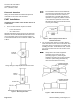
Slip-Slip and Flange-Flange ends are for placement
within the exhaust ductwork; Bellmouth ended units
are for mounting onto a fume hood only (Figure 2).
Terminal measurements are included in Table 1 and
Table 2.
Flange-Flange or Slip-Slip Ends Mounted in Duct.
Bellmouth End Mounted on Fume Hood.
Figure 2. Mounting the FHET.
N
NN
NO
OO
OT
TT
TE
EE
E:
::
:
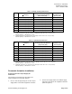
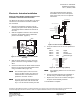
For installations other than the Bellmouth
unit, which is mounted directly to the fume
hood, the FHET must have at least 2 ½
duct diameters of straight rigid ductwork
upstream of it (Figure 3). Failure to have 2
½ duct diameters upstream of the FHET
will adversely affect the flow measurement,
accuracy and stability.
Figure 3. FHET Properly Installed after an
Elbow Duct Section.
2. Use accepted trade practice to weld or bolt the
ends of the FHET to the duct or fume hood. Seal
and check all duct connections for air leaks after
installing the FHET. For Bellmouth units, remove
any excess sealant from the inner surface of the
Bellmouth.
N
NN
NO
OO
OT
TT
TE
EE
E:
::
:
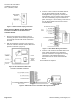
Always mount the FHET equipment
enclosure on the side of the duct
(vertically) (Figure 4). Mounting the
equipment enclosure on the top or bottom
of the duct (horizontally) will adversely
affect the measurement accuracy.
Figure 4. FHET Installed Properly.