
Installation Instructions
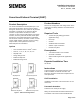

Document No. 546-00011
Installation Instructions
Rev. 2, October, 1999
Siemens Building Technologies, Inc.
Page 3 of 5
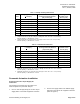
Table 1. LGH Slip and Flange Dimensions.
Duct
Size
Length (L) Inches (mm)
+ 0.06 (1.5)
Slip End Outside Diameter (O.D.)
or Flange End Inside Diameter
(I.D.) Inches (mm)
Flange
Bolt Hole Circle
Size In. (mm)
6 16.00 (406.4) 5.88 (149.4) 7.375 (187.3)
7 16.00 (406.4) 6.88 (174.8) 8.5 (215.9)
8 16.00 (406.4) 7.88 (200.2) 9.5625 (242.9)
9 19.50 (495.3) 8.88 (225.6) 10.625 (269.9)
10 19.50 (495.3) 9.88 (251.0) 11.8125 (300)
11 20.50 (520.7) 11.88 (301.8) 14 (355.6)
12 20.50 (520.7) 11.88 (301.8) 14 (355.6)
14 23.00 (584.2) 13.88 (352.6) 16 (406.4)
1. Provide a minimum of 2.5 duct diameters of straight rigid duct directly upstream.
2. Flanged connection is 1.25” (31.75 mm) for 6” through 10” sizes. OD = O.D. + 2.5” (63.5 mm).
Bolt hole quantity = 6, Bolt hole size = 0.375”.
3. Flanged connection is 1.5” (38.1 mm) for 11” through 14” sizes. OD = O.D. + 3.0” (76.2 mm).
Bolt hole quantity = 8, Bolt hole size = 0.4375”.
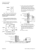
Table 2. LGH Bellmouth Dimensions.
Duct
Size
Length (L) Inches (mm)
+ 0.06 (1.5)
Slip End Outside Diameter (O.D.)
or Flange End Inside Diameter
(I.D.) Inches (mm)
Bellmouth
Bolt Hole Circle
Size In. (mm)
6 18.56 (471.4) 5.88 (149.4) 11.3750 (288.9)
7 18.56 (471.4) 6.88 (174.8) 12.50 (317.5)
8 18.56 (471.4) 7.88 (200.2) 13.5625 (344.5)
9 22.06 (560.3) 8.88 (225.6) 14.625 (371.5)
10 22.06 (560.3) 9.88 (251.0) 15.8125 (401.6)
11 23.06 (585.7) 11.88 (301.8) 18.00 (457.2)
12 23.06 (585.7) 11.88 (301.8) 18.00 (457.2)
14 25.56 (649.2) 13.88 (352.6) 20.00 (508)
1. Provide a minimum of 2.5 duct diameters of straight rigid duct directly upstream.
2. Bellmouth connection is 1.25” (31.75 mm) for 6” through 10” sizes. OD = O.D. + 2.5” (63.5 mm).
Bolt hole quantity = 6, Bolt hole size = 0.375”.
3. Bellmouth connection is 1.5” (38.1 mm) for 11” through 14” sizes. OD = O.D. + 3.0” (76.2 mm).
Bolt hole quantity = 8, Bolt hole size = 0.4375”.
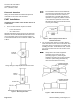
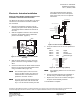
Pneumatic Actuation Installation
Provision of the 18 to 30 psi Supply Air
Connection
One supply air connection must be made to the
FHET to operate the pneumatic damper.
1. Use 1/4- inch OD poly tubing for an 18 to 30 psi
supply airline to the FHET equipment enclosure.
2. Connect the supply airline to the barbed supply
inlet port on the side of the equipment enclosure
(Refer to Figure 5).