
Installation Instructions

Document No. 546-00011
Installation Instructions
Rev. 2, October, 1999
Page 4 of 5
Siemens Building Technologies, Inc.
Figure 5. FHET Pneumatic Piping Connection.
Wiring the AO-P Module and the Differential
Pressure Transmitter to the Fume Hood
Controller Board.
1. Remove the equipment enclosure cover by
loosening the quick release butterfly fasteners.
The butterfly fasteners will remain attached to
the cover.
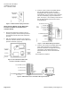
2. With the equipment enclosure cover removed,
locate the Lab AO-P module and the differential
pressure transmitter. (Figure 6).
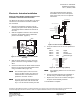
Figure 6. AO-P Module and Differential
Pressure Transmitter Locations.
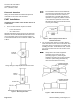
3. Connect a three conductor 20 AWG cable for
the Lab AO-P Module through the wiring
bushing/knockout. (Figure 6). If desired, the
wiring bushing can be removed and a standard
1/2- inch conduit fitting may be installed in its
place. See Figure 7 for the wiring connections to
the Lab AO-P Module from the Fume Hood
Controller Board.
Figure 7. AO-P Module Wiring Connections.
4. Connect a two conductor 20 AWG cable to the
Fume Hood Controller for the differential
pressure transmitter. See Figure 8 for wiring
connections to the differential pressure
transmitter from the Fume Hood Controller
Board.
The installation is complete.
Figure 8. Differential Pressure Transmitter Wirirng Connections.