
Installation Instructions

Document No. 546-00011
Installation Instructions
Rev. 2, October, 1999
Information in this publication is based on current specifications. The company reserves the right to make changes in specifications and
models as design improvements are introduced. Teflon is a registered trademark of DuPont. ©
2009 Siemens Industry, Inc.
Siemens Industry, Inc.
1000 Deerfield Parkway
Buffalo Grove, IL 60089-4513
U.S.A.
Document No.: 546-00011
Printed in the U.S.A.
Page 5 of 5
Electronic Actuation Installation
Wiring the AO-E Module and differential pressure
transmitter to the Fume Hood Controller.
The Electronic Actuator is provided with a pre-wired
connector that is attached to the AO-E module on
the J4 terminal.
1. Remove the equipment enclosure cover by
loosening the quick release butterfly fasteners.
The butterfly fasteners will remain attached to
the cover.
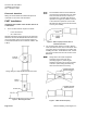
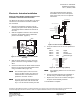
2. With the equipment enclosure cover removed,
locate the AO-E module and the differential
pressure transmitter. (Figure 9).
1 1 11
11.75
14.5
AO - E
MODULE
FUM0310R1
ACTUATOR
DIFFERENTIAL
PRESSURE
TRANSMITTER
(USED ON FHET)
Figure 9. Electronic Actuator and AO-E Module
Assembly.
3. Wire the AO-E module to a source of 24 Vac
power to terminal J1 using 18 AWG or larger
wires.
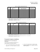
4. Connect the wire from the AO-E module terminal
block J2, to the FHC board terminal block TB3
using a 20 AWG cable. (Figure 10).
N
NN
NO
OO
OT
TT
TE
EE
E:
::
:
This actuator requires a 25 VA, 24 Vac
source. DO NOT connect any other non-
isolated devices to the transformer that
powers the electronic actuator.
N
NN
NO
OO
OT
TT
TE
EE
E:
::
:
The FHC and LRC must be powered by a
separate power trunk from the FFM and
any 0 – 10 Vdc actuator used by the LRC.
The Lab Controls Electronic Actuator
Assemblies can be on the same power
trunk as the FHC, LRC or on a separate
transformer.
24 VAC
TRUNK
AO
-
E MODULE
PLUG
ELECTRONIC
ACTUATOR
FUM0309R2
Com (AC)
DO3 (spare)
Com (AC)
DO2 Exhaust (AO-E: retract)
Com (AC)
DO1 Supply (AO-E: extend)
DI-1 (-)
DI-1 (+)
FUME HOOD CONTROLLER
TB-3
Blue
Red
Green
Yellow
Black
Retract
Extend
0-10 V
GND
4-20 mA
Blue
Red
24 VAC, 25 VA
Extend
COM
Retract
1
2
1
2
3
4
5
8
7
6
5
4
3
2
1
1
2
3
1
2
3
N
H
E
J4
J5
J2
J3
J1
Figure 10. FHC and AO-E Module Wiring.
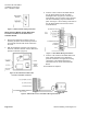
5. Verify the switches are set for FHC operation as
follows:
SW2-1 OFF Digital
SW2-2 OFF Normal
SW2-4 OFF Fail-Retracted
SW2-5 OFF LRC/FHC logic
Standard Logic
Fail Last Position
Retract
Test
Analog
LRC/FHC Logic
Fail retracted
Extend
Norm
Digital
SW1
SW2
4-20 ma
0-10 vdc
FUM0316R2
Figure 11. Switch Settings (default).
N
NN
NO
OO
OT
TT
TE
EE
E:
::
:
Any remaining switches are not used in the
application.
6. Connect the differential pressure transmitter to
the FHC using a 20 AWG cable. (Figure 8).
7. Replace the cover on the enclosure and tighten
the quick release butterfly fasteners.
The installation is complete.