
Operating Instructions

Chapter 3 – Point Database
15
Siemens Industry, Inc.
Owner's Manual
125-5084
06/30/2015
Chapter 3 – Point Database
Chapter 3 presents a description of the LCM-OAVS Room Pressurization with Slow-
acting Supply Damper, Venturi Exhaust Actuation and Hot Water Reheat point
database, including point descriptors, point addresses, and a listing of applications in
which each point is found.
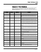
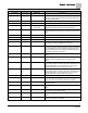
Descriptor
Address
1
Application
Description
CTLR ADDRESS
01
All
Identifies the controller on the LAN trunk.
APPLICATION
02
All
Identification number of the program running in the controller.
TEMP OFFSET
03
All
Room temperature offset is a user-adjustable offset that will
compensate for deviations between ROOM TMP and CTL
TEMP.
ROOM TEMP
{04}
2
All
Actual reading from the room temperature sensor.
OCC DIF STPT
05
2924, 2930
The temperature setpoint, in degrees, that the controller
maintains during occupied periods in cooling mode if a room
temperature sensor setpoint dial is not present or is not used.
UOC DIF STPT
06
2924, 2930
The temperature setpoint, in degrees, that the controller
maintains during unoccupied periods in cooling mode if a room
temperature sensor setpoint dial is not present or is not used.
RM STPT MIN
07
2924, 2930
The minimum temperature setpoint, in degrees, that the
controller can use from the setpoint dial. This overrides any
temperature set point from the set point dial that falls below this
minimum.
RM STPT MAX
08
2924, 2930
The maximum temperature setpoint in degrees that the
controller can use from the setpoint dial. This overrides any
temperature setpoint from the setpoint dial that falls above this
maximum.
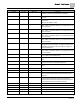
TEMP CTL VOL
{09}
2924, 2930
Amount of supply airflow that the temperature control sequence
determines is necessary to regulate the room temperature.
TABLE FLOW
{10}
2924, 2930
Editable table statement point allowing low flow functionality, a
value below 350 cfm is entered.
OCC ENA
12
2924, 2930
An analog point that determines if and what occupancy button
is enabled.
RM STPT
{13}
2
All
The temperature setpoint in degrees from the room
temperature sensor (not available on all temperature sensor
models).
AI 4
{14}
All
Spare analog input (0-10V or 4-20 mA).
HOOD SIG AI 3
{15}
2924, 2930
Voltage that tells the LCM how much air the fume hood(s) is
exhausting.
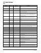
AI 3
{15}
2997
Spare analog input (0-10V or 4-20 mA).
VENT ALM DEL
16
2924, 2930
Delay period that prevents “nuisance alarms” on the air change
rate.
ALARM ENA
17
2924, 2930
An analog point that determines if and what alarm activates
ALARM DO7.
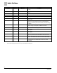
START
18
6724
The starting point in the temperature control sequence for the
reheat valve to supply heating to the room.