
Operating Instructions

Chapter 3 – Point Database
17
Siemens Industry, Inc.
Owner's Manual
125-5084
06/30/2015
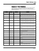
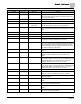
Descriptor
Address
1
Application
Description
DIF ALM DBD
38
2924, 2930
Setting for the controller’s alarm; should be set lower than VOL
DIF STPT to avoid losing pressurization completely.
DIF ALM DEL
39
2924, 2930
Alarm delay point to prevent “nuisance alarms” on the flow
difference.
AVS FAIL MODE
40
2924, 2930
Indicates the desired position of the damper if the airflow
sensor(s) fail.
Valid input: CLOSED or OPEN.
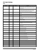
DO 1
{41}
All
Digital output 1 controls a 24 Vac load with an ON or OFF
status. If Motor 1 is enabled, then DO 1 is coupled with DO 2 to
control an actuator.
DO 2
{42}
All
Digital output 2 controls a 24 Vac load with an ON or OFF
status. If Motor 1 is enabled, then DO 2 is coupled with DO 1 to
control an actuator.
DO 3
{43}
All
Digital output 3 controls a 24 Vac load with an ON or OFF
status. If Motor 2 is enabled, then DO 3 is coupled with DO 4 to
control an actuator.
DO 4
{44}
All
Digital output 4 controls a 24 Vac load with an ON or OFF
status. If Motor 2 is enabled, then DO 3 is coupled with DO 4 to
control an actuator.
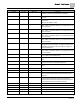
TRACK METHOD
45
2924, 2930
Determines whether the controller uses FLOW or STPT flow
tracking. When the value is STPT, the supply flow follows the
GEN EXH STPT. When the value is FLOW, the supply flow
follows GEN EXH VOL.
DO 5
{46}
All
Digital output 5 controls a 24 Vac load with an ON or OFF
status. If Motor 2 is enabled, then DO 3 is coupled with DO 4 to
control an actuator.
ALARM DO 7
{47}
2924, 2930, 2997
Intended to drive local alarm device (horn, light, etc.). Function
set up by setting alarm enable points.
DO 7
{47}
2997
Digital output 7 controls a 24 Vac load with an ON or OFF
status.
AUTOZERO DO 8
{48}
2924, 2930, 2997
Drives the Offboard Air Module(s) in order to calibrate the flow
sensor(s). Do not use or manually set this point.
DO 8
{48}
2997
Digital output 8 controls a 24 Vac load with an ON or OFF
status.
VALVE CMD
{49}
2924, 2930
State of the reheat valve. Represents how far the valve is open.
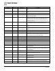
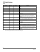
DISCH MIN
51
2930
Minimum discharge temperature setting.
MAXHOOD VOL
52
2924, 2930
The Fume Hood exhaust airflow value that corresponds to 10
Volts input signal. Must be setup to match the hood control
equipment.
TOTL EXHAUST
{53}
2924, 2930
Point 30 + Point 52 + Point 89. This value is the sum of the
measured value of the airflow from the room through the
general exhaust terminal, the airflow through the fume hoods,
and any exhaust flows not connected to the LCM.
GEX FLO COEF
54
2924, 2930
Calibration parameter for airflow sensor.
FLOW COEFF 2
54
2997
Calibration parameter for airflow sensor.
AO 2
{55}
All
Control signal for Venturi Supply Valve (0 - 10V).
GEX DMPR AO 3
{56}
2924, 2930
Control signal for Venturi General Exhaust Valve (0 - 10V).
AO 3
{56}
2997
Analog output (0-10 Vdc) optional control.