
Operating Instructions

Chapter 3 – Point Database
18
Siemens Industry, Inc.
Owner's Manual
125-5084
06/30/2015
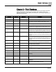
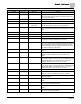
Descriptor
Address
1
Application
Description
VALVE CLOSED
57
2924, 2930
Setup point. Tells the LCM what voltage fully closes the reheat
valve.
VALVE OPEN
58
2924, 2930
Setup point. Tells the LCM what voltage fully opens the reheat
valve.
DISCH MAX
59
2930
Maximum discharge temperature setting.
GEXDUCT AREA
60
2924, 2930
Internal cross-sectional area of the general exhaust duct where
the flow sensor is installed.
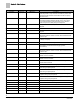
DUCT AREA 2
60
2997
Area, in square feet (square meters), of the duct where the air
velocity sensor is located. This is a calculated value (calculated
by the field panel or computer being used) that depends on
duct shape and size. It is used in calculating all points in units
of CFM, CF, LPS and L.
OTHER SUP
{61}
2924, 2930
Value of any supply airflows not connected to the LCM. Must
be entered to the controller to account for flows it cannot
detect.
ROOM P GAIN
63
2930
Proportional feedback gain used to tune the room temperature
control.
ROOM I GAIN
64
2930
Integral feedback gain used to tune the room temperature
control.
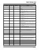
UOC GEX MAX
{67}
2924, 2930
Maximum general exhaust in unoccupied mode.
UOC GEX MIN
{68}
2924, 2930
Minimum general exhaust in unoccupied mode.
TOTL SUPPLY
{69}
2924, 2930
Point 35 + Point 61. This is the measured value of the airflow
delivered to the room by the supply terminal, plus the value of
any supply airflows not connected to the LCM.
SUP P GAIN
70
2924, 2930
Feedback gain. Used to tune supply flow control.
UOC SUP MAX
{71}
2924, 2930
Maximum supply in unoccupied mode.
UOC SUP MIN
{72}
2924, 2930
Minimum supply in unoccupied mode.
CTL STPT
{73}
2924, 2930
The setpoint for the Room Temperature PID Loop.
HOOD VOL
{74}
2924, 2930
The airflow signal from the fume hood(s).
DISCH STPT
{75}
2930
Discharge temperature setpoint.
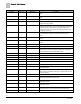
VOLUME STATE
76
2924, 2930
Determines type of control, VAV or CV, during occupied and
unoccupied modes.
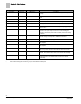
DO 6
{77}
All
Digital output 6 controls a 24 Vac load with an ON or OFF
status. If Motor 3 is enabled, then DO 5 is coupled with DO 6 to
control an actuator.
CTL TEMP
{78}
All
The temperature input for the Room Temperature PID Loop.
TEMP LOOPOUT
{79}
2924, 2930
The value calculated by the room temperature PID algorithm. It
indicates the thermal load on the room.
DISCH P GAIN
80
2930
The proportional feedback gain used to tune the discharge
temperature control.
DISCH I GAIN
81
2930
The integral feedback gain used to tune the discharge
temperature control.
VOL DIFFRNC
{83}
2924, 2930
The difference between measured airflow into the room, and
measured airflow out. Equal to Point 53 through Point 69).
AI 5
{84}
6724, 6797
Spare Analog input, 10k Ohm thermistor.