
Operating Instructions

Chapter 3 – Point Database
19
Siemens Industry, Inc.
Owner's Manual
125-5084
06/30/2015
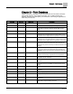
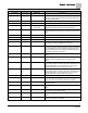
Descriptor
Address
1
Application
Description
DISCH TEMP
{84}
2930
Discharge temp sensor input.
GEX FLO STPT
{85}
2924, 2930
The desired value of the general exhaust. The controller
selects the lowest value that will lead to adequate supply flow,
and correct pressurization.
FAIL LIMIT
86
2924, 2930
Indicates when the air volume is too far away from setpoint.
CAL VENTURI
{87}
2924, 2930
Initiates and displays the initiation status of Venturi calibration.
VOL DIF STPT
{88}
2924, 2930
6754, 6760
The desired value for the flow difference. This value can be
selected and adjusted to achieve room pressurization.
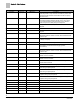
OTHER EXH
{89}
2924, 2930
The value of any exhaust airflows not connected to the LCM.
Must be entered to the controller to account for flows it cannot
detect.
OCV ALM LVL
90
2924, 2930
Ventilation alarm level in occupied mode.
UCV ALM LVL
91
2924, 2930
Ventilation alarm level in unoccupied mode.
VENT ALM
{92}
2924, 2930
Alarm point indicates inadequate air change rate.
SUP FLO STPT
{93}
2924, 2930
The desired value of the supply flow, chosen by the controller,
to achieve the correct flow difference for the room.
CAL AIR
{94}
All
YES commands the controller to go through calibration
sequence for the air velocity transducers. YES is also displayed
when the calibration sequence is started automatically. CAL
AIR automatically returns to NO after the calibration sequence
is completed. Valid input: YES or NO.
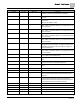
CAL SETUP
95
2924, 2930, 2997
The configuration setup code for the calibration sequence
options.
CAL TIMER
96
2924, 2930, 2997
Time interval, in hours, between the calibration sequence
initiations if a timed calibration option is selected in CAL
SETUP.
SUPDUCT AREA
97
2924, 2930
Area, in square feet (square meters), of the supply duct where
the air velocity sensor is located. This value is calculated by the
field panel depending on duct shape and size. It is used in
calculating all points in units of cfm, CF, lps, and L.
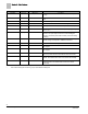
DUCT AREA 1
97
2997
Area, in square feet (square meters), of the supply duct where
the air velocity sensor is located. This value is calculated by the
field panel depending on duct shape and size. It is used in
calculating all points in units of cfm, CF, lps, and L.
LOOP TIME
98
2924, 2930
The time, in seconds, between control loop calculations.
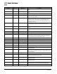
ERROR STATUS
{99}
All
The status code indicating any errors detected during controller
power up. A status of 0 indicates there are no problems.
SENSOR SEL
104
All
Room unit configuration point and thermistor type selection,
values are additive.
VENTURI ACT
105
2924, 2930
Setup point. Indicates NOPEN or NCLOSE for Venturi Air
Valves.
MODHTG FLO
106
2924, 2930
The minimum flow in feet per minute needed for safety
purposes when using electric reheat.
DO DIR.REV
107
All
Reverses the output state for selected non-motor digital
outputs.
RM RH
{108}
All
This point may be used in a control strategy as humidity levels
varies in the room being controlled.