LCM-OAVS Room Pressurization with Slowacting Venturi Air Valves (One Exhaust, One Supply), Hot Water Reheat and BTU Compensation, Application 2928 Application Note 140-1302 2015-07-07 Building Technologies
Table of Contents Overview ............................................................................................................................. 5 Hardware Inputs .................................................................................................................. 6 Hardware Outputs ................................................................................................................ 7 Ordering Notes .............................................................................
Alarms ............................................................................................................................ 35 Ventilation Alarm ................................................................................................ 35 Pressurization Alarm .......................................................................................... 36 Local Annunciation ............................................................................................. 36 Network Annunciation.......
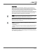
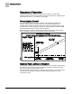
Overview Hardware Inputs Overview Application 2928 controls pressurization, ventilation, and room temperature in a laboratory room served by one single-duct supply terminal with a reheat coil, one general exhaust terminal, and up to six fume hoods (multiple fume hood flow signals must be averaged using an averaging and scaling module. Pressurization is controlled by maintaining a selected difference between supply and exhaust airflows.
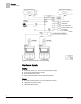
Overview Hardware Inputs Ventilation and Pressurization Control Drawing. Hardware Inputs Analog Air velocity sensor (s) – (one or two depending on setup) Fume hood controller input or FFM Room temperature sensor Discharge Temperature Sensor (10K Ω thermistor) Digital Occupancy button (option on room temperature sensor) (Optional) Occupancy switch (Optional) Alarm switch 6 Siemens Industry, Inc.
Overview Hardware Outputs Hardware Outputs Analog Reheat valve Supply Venturi Air Valve General exhaust Venturi Air Valve Digital Autozero Solenoid in Offboard Air Module (DO 8) (Optional) Alarm Ordering Notes 550-767DN LCM-OAVS Room Pressurization with Two Slow-acting Venturi Air Valves (One Supply, One Exhaust) and Hot Water Reheat Requires Offboard Air Module(s) – order and ship separately 550-819B Offboard Air Module (OAM) – order and ship separately 7 Siemens Industry, Inc.
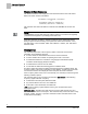
Sequence of Operation Pressurization Control Sequence of Operation The following paragraphs present the sequence of operation for LCM-OAVS Application 2628: VAV Room Pressurization with BTU Compensation, HW Reheat and Slow Venturi Air Valves — One Exhaust, One Supply. Pressurization Control The goal of pressurization control is to maintain a fixed difference between the volumes of total supply air and total exhaust air (see the following figure).
Sequence of Operation Optional Rate Limiting of Actuators To deal with the possibility of unequal flow rate changes, the application includes two new points which allow field adjustment to slow down actuators. SUP MAX RATE effectively limits the speed of the supply actuator; GEX MAX RATE effectively limits the speed of the exhaust actuator. SUP MAX RATE and GEX MAX RATE should be changed to values other than 0 only after a thorough analysis has been made of the job specific scenarios.
Sequence of Operation Room Airflow Balance Room Airflow Balance The difference between total supply flow and total exhaust flow is the room airflow balance as shown in these calculations: VOL DIFFRNC = TOTL EXHAUST – TOTL SUPPLY -orVOL DIFFRNC = (HOOD VOL + GEX AIR VOL + OTHER EXH) – (SUP AIR VOL + OTHER SUP) The controller uses these calculations to maintain VOL DIFFRNC at the VOL DIF STPT.
Sequence of Operation Active Flow Minimums and Maximums NOTE: The displayed OCC/UNOCC status of the LCTLR point does not always match the occupancy status of the controller. To get an actual indication of occupancy status, OCC.UNOCC must be used. If network commands are not required and occupancy will be set by sources in the room, set NET OCC CMD to UNOCC. If set to OCC, the controller will stay in occupied mode.
Sequence of Operation VAV versus CV Control When OCC.UNOCC equals UNOCC: The active supply airflow minimum equals UOC SUP MIN. The active supply airflow maximum equals UOC SUP MAX. The active general exhaust airflow minimum equals UOC GEX MIN. The active general exhaust airflow maximum equals UOC GEN MAX. VAV versus CV Control In Application 2928, VAV means that temperature is controlled by varying flow in conjunction with the reheat valve.
Sequence of Operation Flow Tracking – Supply Tracks Exhaust vs. Exhaust Tracks Supply NOTE: If desired, the LCM can be used without any fume hoods attached. In this case, MAX HOOD VOL should be set to 0 cfm to disable the alarming that would occur if the fume hood flow input drops below 1 Vdc. Flow Tracking – Supply Tracks Exhaust vs.
Sequence of Operation Calculating Exhaust Flow Setpoint TRACK METHOD TRACK METHOD is a point associated with TRACK MODE. TRACK MODE determines which airflow (supply or general exhaust) gets tracked and which airflow does the tracking. TRACK METHOD determines how tracking is accomplished. If TRACK MODE is set to ETS and TRACK METHOD is set for FLOW tracking, the general exhaust flow setpoint is calculated according to the measured value, SUP AIR VOL.
Sequence of Operation Calculating Supply Flow Setpoint When Exhaust Tracks Supply (ETS) flow tracking is used, the general exhaust airflow setpoint is calculated the same during both VAV and CV operation, as follows: To calculate GEX FLO STPT, the controller determines the general exhaust airflow value that pressurizes the room based on the values of VOL DIF STPT, OTHER EXH, OTHER SUP and either SUP FLO STPT or SUP AIR VOL depending on the value of TRACK METHOD.
Sequence of Operation Ventilation – VAV Mode Ventilation – VAV Mode During VAV operation, the ventilation works as follows: OCC SUP MIN, the occupied supply minimum, is used to ensure that the room receives enough supply air for proper ventilation during the occupied mode. UOC SUP MIN is used to ensure that the room receives enough supply air for proper ventilation during the unoccupied mode.
Sequence of Operation Airflow Control When calibration is in progress, CAL AIR equals YES. After calibration, CAL AIR returns to NO. The application uses Autozero Modules connected to AUTOZERO DO8. This means that the supply and general exhaust flow control devices do not close during calibration of the transducers. NOTE: The LCM does not monitor Fume Hood flow changes for 3 seconds during AVS calibration.
Sequence of Operation Airflow Control Table Statement and Feedback Loop Interaction Supply Air Velocity Control A table statement and the supply air velocity feedback control loop work together to control the supply air velocity. (The table statement values are generated automatically during calibration of the supply Venturi Air Valve.
Sequence of Operation Venturi Air Valve Calibration (Mode 1, 3) NOTE: If HI and LO LIMIT are set equal, then the feedback loop will always be active as long as the general exhaust air flow is greater than first element in the Venturi table (such as 300 or 350 cfm) The interaction between the table statement and the general exhaust air velocity feedback loop can be summarized as follows: When the general exhaust air volume is near setpoint, the table statement controls it.
Sequence of Operation Table Access Feature (Mode 1, 3) When calibration is complete, the EEPROM automatically stores a table statement of voltages (no loss of values upon power failure) that will be output to the AO point, SUP DMPR AO2 or GEX DMPR AO3, to drive the actuator. Table values are the result of the application’s analysis of the voltages that drove the actuator during calibration and the resulting airflow values in cfm.
Sequence of Operation Table Access Feature (Mode 1, 3) a) These voltage/flow values constitute the “low flow” element (or “point”) for the Supply and the General Exhaust Venturi Air Valves. They are shown here with factory default values. They are not altered during calibration—they must be set manually. However, they only need to be set if the Venturi Air Valve is going go be operating at low flow settings of less than 350 fpm. Otherwise, they can be left at default and ignored.
Sequence of Operation Venturi Table Evaluation and Editing (Mode 1, 3) The first pair of voltage/flow values—the low flow point—is not generated; it must be set manually. Note, however, that this low flow point can be entered only after other non-zero points are in the table as a result of manual edits, or from a prior Venturi auto calibration sequence. This application has a table statement edit feature that allows you to view and edit the voltage/flow values in the table.
Sequence of Operation Venturi Table Evaluation and Editing (Mode 1, 3) NOTE: An exception to this rule is when active values cannot be manually overridden. The first element in the active portion of the table—the low flow point—can be edited directly. The Table Venturi Air Valve Table Statement explains this in more detail. 2. Edit the inactive table values.
Sequence of Operation Venturi Table Evaluation and Editing (Mode 1, 3) Venturi Air Valve Table Statement V TABLE PT 1 Setting V TABLE PT to 1 takes the flow (cfm) and voltage values from the first element of the active supply table and displays them in TABLE FLOW and TABLE VOLTS where they can be edited. (This is the only active supply element (or “point”) that can be directly edited.) Flow and voltage values are not allowed to exceed those in active supply point 2.
Sequence of Operation Venturi Table Evaluation and Editing (Mode 1, 3) Venturi Air Valve Table Statement V TABLE PT Description 32 - 46 This portion of the table (32 through 46) can be viewed but not edited directly. When a point is selected (that is, when V TABLE PT is set to a value 32 through 46), the corresponding flow and voltage values are displayed in TABLE FLOW and TABLE VOLTS.
Sequence of Operation PID Only (Mode 2) PID Only (Mode 2) NOTE: The default P gain value is intended for PID operation in conjunction with the Venturi table. The P gain and Venturi table work together to provide an appropriate response to setpoint changes. When operating without the Venturi table in PID Only mode, the application is slower to respond. Therefore, you should adjust the P gain as needed when operating in PID Only mode to ensure acceptable performance.
Sequence of Operation Open Loop (Mode 3) It may not be necessary to enter 0 values since 0 values are initially in the table by default when direct acting is selected. Point Flow Volt 1 0 10.0 2 0 10.0 15 0 10.0 16 1200 0.0 Example 2 - Table with CFM End Limits – reverse acting It may not be necessary to enter 10.0 values since 10.0 values are initially in the table by default when reverse acting is selected.
Sequence of Operation Operating Without a Supply or Exhaust 8 340 3.2 9 390 3.5 10 521 3.8 11 531 4.1 12 598 4.9 13 691 5.8 14 798 7.0 15 0 0 16 1200 10 Example 5 - Multi-point Table The point values above are for the exhaust table. Open loop supply operation is similar, but the points used are 1 through 16; not 30 through 46. Since the actual airflow being measured is 0, the heating safety requirement for minimum airflow is not met and heating will not occur.
Sequence of Operation Room Temperature and Setpoint In a 12-inch diameter duct and a typical flow coefficient of .7, 300 fpm equates to 158 cfm. 12 inch diameter = .75 sq ft .75 sq ft * 300 fpm * .7 = 158 cfm In an 8-inch diameter duct and a typical flow coefficient of .7, 300 fpm equates to 74 cfm. 8 inch diameter = .35 sq ft .35 sq ft * 300 fpm * .7 = 74 cfm If the application uses hot water heat rather than electric heat, then MODHTG FLO may be set lower than the default value of 300.
Sequence of Operation Room Unit Identification CTL TEMP = ROOM TEMP + TEMP OFFSET Example If the actual room temperature is 72.0°F, and the value of ROOM TEMP is 73.0°F, then the value entered into TEMP OFFSET is -1.0. In this case, the value of ROOM TEMP would read 73.0°F, but the value of CTL TEMP would read 72.0°F. Room Unit Identification For Analog Room Units (Series 1000) – The revision number is visually identified by its case.
Sequence of Operation Temperature Control Loops SENSOR SEL Value * Description 0 Analog Room Unit, 10K 1 Select Digital Room Unit (for temperature sensing and setpoint dial), 10K 2 Relative Humidity (RH) sensing, 10K 3 Digital Room Unit, RH, 10K 4 CO2 sensing, 10K 5 Digital Room Unit, CO2, 10K 7 Digital Room Unit, RH, CO2, 10K 8 Analog Room Unit, 100K 9 Digital Room Unit, 100K 11 Digital Room Unit, RH, 100K 13 Digital Room Unit, CO2, 100K 15 Digital Room Unit, RH, CO2, 100k 16 (N
Sequence of Operation BTU Calculations maintain the discharge temperature set in DISCH STPT. See BTU Calculations – VAV Mode and BTU Calculations – Constant Volume Mode. BTU Calculations NOTE: BTU Compensation vs. Room Temperature Sensor (RTS) Control – In applications that do not include BTU Compensation, the heating loop modulates the heating valve directly using RTS control.
Sequence of Operation BTU Calculations CTL STPT = 70°F: OCC.UNOCC = UNOCC If TEMP LOOPOUT = and SUP AIR VOL = then DISCH STPT = Formula for DISCH STPT: CTL STPT + (TEMP LOOPOUT x 100% ÷ SUP AIR VOL) 10°F UOC SUP MAX 80°F 70° + (10° x 100% ÷ 100%) 10°F 0.5 ´ UOC SUP MAX 90°F 70° + (10° x 100% ÷ 50%) –5°F 0.
Sequence of Operation BTU Calculations BTU Calculations – Constant Volume Mode During the Constant Volume Mode, the BTU Compensator operates as follows: During Constant Volume operation, the controller adjusts the supply air temperature set point as necessary to maintain CTL TEMP at CTL STPT. The room temperature PID loop calculates the value of TEMP LOOPOUT. This value is used to adjust the value of the supply air temperature set point.
Sequence of Operation Alarms Alarms The controller is equipped with ventilation and pressurization alarms. It does not contain temperature alarms. The controller’s alarms are designed to: Inform room occupants of hazards. Inform building operation personnel that the system is not functioning correctly. Supply data for documenting laboratory safety records through trending. These alarms can be annunciated locally and/or broadcast across a network.
Sequence of Operation Alarms Pressurization Alarm The pressurization alarm, VOL DIF ALM indicates that the difference between supply and exhaust flow is not what it should be, or that the controller can't calculate the flow difference, VOL DIFFRNC, because it has lost a flow signal. The Figure Failure Mode Sequence lists reasons why VOL DIFFRNC may fail. The pressurization alarm point is turned on when at least one of the following conditions occurs: VOL DIFFRNC has a status of Failed.
Sequence of Operation Alarms ALARM ENA Values. ALARM ENA 5 Vent Alarm and Dif Alarm are enabled. 6 Alarm Switch and Dif Alarm are enabled. 7 Vent Alarm, Alarm Switch, and Dif Alarm are all enabled. NOTE: If ALARM ENA is set greater than 7, it will default to 0. ALM ENA is additive. For example, if ALM ENA equals 5, then either a ventilation or a pressurization alarm will activate ALARM DO7, but the alarm switch will not.
Sequence of Operation Valve Position on Return from Power Failure Valve Position on Return from Power Failure On a return from power failure, the AOs remain OFF for 5 seconds prior to resuming control. Because of this it is recommended that the Supply Valve be set to Normally Closed for rooms where negative or neutral pressurization is required and Normally Opened for positively pressurized rooms.
Sequence of Operation Fail Mode Operation The first seven values of AVS FAILMODE (0 through 6) describe specific actions taken when an AVS fails. For example, if AVS FAILMODE equals 5, then whenever an AVS fails, the supply Venturi Air Valve will always close and the general exhaust Venturi Air Valve will always open. The last two values of AVS FAILMODE do not describe specific actions; that is, when an AVS fails, the supply and general exhaust will react differently depending on the circumstances.
Sequence of Operation Fail Mode Operation Air Velocity Sensors – If one or both of the LCM air sensor signals (SUP AIR VOL, GEX AIR VOL) are out of range (for example, improper wiring to/from the Offboard Air Module(s), tubing not connected or connected backward), then the actions of the supply and general exhaust Venturi Air Valves will depend on the value of AVS FAILMODE. Once GEX AIR VOL and SUP AIR VOL are normal, the supply and general exhaust Venturi Air Valves return to normal operation.
Sequence of Operation Application Notes Application Notes Supply Only - Operating Without a General Exhaust Box This application can operate without a general exhaust box. If a general exhaust box is not being controlled, set TRACK METHOD to FLOW and set the following points: TRACK MODE to 3. – Without a fume hood attached, use a value of 3 = ETS (exhaust tracks supply) Flow Tracking, should be used for both the occupied and unoccupied modes.
Sequence of Operation Wiring Diagrams CAUTION A separate power supply is required if a 4-20 mA sensor is used. Failure to follow wiring precautions will result in equipment damage. Wiring for AI with a 4 to 20 mA Sensor. CAUTION Each 4-20 mA sensor requires a SEPARATE dedicated power limited 24 Vdc power supply. DO NOT use the same transformer to power both the sensor and the controller.
Sequence of Operation Wiring Diagrams NOTE: Thermistor inputs are 10K (default) or 100K software selectable (AI X). BACnet LCM-OAVS Slow Actuation Venturi Supply/Venturi Exhaust with BTU Compensation – Application 2928 Wiring Diagram. 43 Siemens Industry, Inc.
Point Database Application 2928 Point Database Application 2928 Point Number Descriptor Factory Default (SI Units) Eng Units (SI Units) Slope (SI Units) Intercept (SI Units) On Text Off Text 1 CTLR ADDRESS 99 -- 1 0 -- -- 2 APPLICATION 2997 -- 1 0 -- -- 3 TEMP OFFSET 0.0 (0.0) DEG F (DEG C) 0.25 (0.14) -31.75 (-17.78) -- -- {04} ROOM TEMP 74.0 (23.44888) DEG F (DEG C) 0.25 (0.14) 48.0 (8.88888) -- -- 5 OCC DIF STPT 400 (188.7599) CFM (LPS) 4 (1.
Point Database Application 2928 Point Number Descriptor Factory Default (SI Units) Eng Units (SI Units) Slope (SI Units) Intercept (SI Units) On Text Off Text {31} OCC SUP MAX 3400 (1604.46) CFM (LPS) 4 (1.8876) 0 -- -- {32} OCC SUP MIN 340 (160.446) CFM (LPS) 4 (1.8876) 0 -- -- {33} OCC GEX MAX 1100 (519.09) CFM (LPS) 4 (1.8876) 0 -- -- {34} OCC GEX MIN 600 (283.14) CFM (LPS) 4 (1.8876) 0 -- -- {35} SUP AIR VOL 0 (0.0) CFM (LPS) 4 (1.
Point Database Application 2928 Point Number Descriptor Factory Default (SI Units) Eng Units (SI Units) Slope (SI Units) Intercept (SI Units) On Text Off Text 63 ROOM P GAIN 2 -- 0.05 0 -- -- 64 ROOM I GAIN 0.001 -- 0.0001 0 -- -- {67} UOC GEX MAX 1000 (471.9) CFM (LPS) 4 (1.8876) 0 -- -- {68} UOC GEX MIN 500 (235.95) CFM (LPS) 4 (1.8876) 0 -- -- {69} TOTL SUPPLY 0 (0.0) CFM (LPS) 4 (1.8876) 0 -- -- 70 SUP P GAIN 0.015 -- 0.
Point Database Application 2928 Point Number Descriptor Factory Default (SI Units) Eng Units (SI Units) Slope (SI Units) Intercept (SI Units) On Text Off Text 96 CAL TIMER 12 HRS 1 0 -- -- 97 SUPDUCT AREA 1.0 (0.09292) SQ. FT (SQ M) 0.025 (0.002323) 0 -- -- 98 LOOP TIME 5 SEC 1 0 -- -- {99} ERROR STATUS 0 -- 1 0 -- -- 104 SENSOR SEL 8 -- 1 0 -- -- 105 VENTURI ACT 1 -- 1 0 -- -- 106 MODHTG FLO 300 (1.524) FPM (MPS) 1 (0.
Point Database (Slave Mode) Application 2997 Point Database (Slave Mode) Application 2997 Point Number Descriptor Factory Default (SI Units) Eng Units (SI Units) Slope (SI Units) Intercept (SI Units) On Text Off Text 1 CTLR ADDRESS 99 -- 1 0 -- -- 2 APPLICATION 2997 -- 1 0 -- -- 3 TEMP OFFSET 0.0 (0.0) DEG F (DEG C) 0.25 (0.14) -31.75(-17.78) -- -- {04} ROOM TEMP 74.0 (23.44888) DEG F (DEG C) 0.25 (0.14) 48.0 (8.88888) -- -- {13} ROOM STPT 74.0 (23.
Point Database (Slave Mode) Application 2997 Point Number Descriptor Factory Default (SI Units) Eng Units (SI Units) Slope (SI Units) Intercept (SI Units) On Text Off Text {84} AI 5 74.0 (23.496) DEG F (DEG C) 0.5 (0.28) 37.5(3.056) -- -- {94} CAL AIR NO -- -- -- YES NO 95 CAL SETUP 4 -- 1 0 -- -- 96 CAL TIMER 12 HRS 1 0 -- -- 97 DUCT AREA 1 1.0 (0.09292) SQ. FT (SQ 0.025 M) (0.
Issued by Siemens Industry, Inc. Building Technologies Division 1000 Deerfield Pkwy Buffalo Grove IL 60089 Tel. +1 847-215-1000 Document ID 140-1302 Edition 2015-07-07 © Siemens Industry, Inc., 2015 Technical specifications and availability subject to change without notice.