
Application

Sequence of Operation
Venturi Air Valve Calibration (Mode 1, 3)
19
Siemens Industry, Inc.
Application Note, App 2928
140-1302
2015-07-07
NOTE:
If HI and LO LIMIT are set equal, then the feedback loop will always be active as long
as the general exhaust air flow is greater than first element in the Venturi table (such
as 300 or 350 cfm)
The interaction between the table statement and the general exhaust air velocity
feedback loop can be summarized as follows:
When the general exhaust air volume is near setpoint, the table statement controls
it.
When the general exhaust air volume is not near its setpoint (either too high or too
low), both the table statement and the general exhaust air velocity feedback loop
work together to bring the general exhaust air velocity close to its setpoint as
quickly as possible.
When the general exhaust air velocity is so low that it cannot be accurately read by
the general exhaust AVS, the table statement controls it.
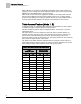
Venturi Air Valve Calibration (Mode 1, 3)
The calibration table for Venturi Air Valve(s) determines the relationship between
airflow and the voltage curve of the actuator. The calibration table initially contains all
zeros by default, that is, it contains no calibration information. This section describes
how the user initiates a calibration sequence that populates the calibration table with
values of flow at given control voltages.
NOTE:
This automatic calibration sequence relies on values from an associated flow sensor.
If running open loop (without a flow sensor), see the
Open Loop Mode
section.
Prerequisites for calibrating Venturi Air Valves:
Fully operational supply and general exhaust airflow systems.
Supply and general exhaust Air Velocity Sensors are calibrated and working
normally (SUP AIR VOL and GEX AIR VOL cannot be Failed).
The supply or general exhaust Venturi Air Valve is calibrated by setting CAL SUP VLV
or CAL GEX VLV to YES. Calibration proceeds automatically and takes about 3
minutes, after which CAL SUP VLV (or CAL GEX VLV) returns to NO. If calibration is
successful, SUP VLV STAT, or GEX VLV STAT, is set to CAL OK. A failed calibration
requires checking the equipment for possible causes—loose or kinked flow sensor
tubes, improper actuator or valve operation, etc.—followed by recalibration.
NOTE:
The factory default values of SUP VLV STAT and GEX VLV STAT is NOTCAL.
NOTCAL means that neither the calibration sequence nor manual entry has been
done. The value of SUP VLV STAT or GEX VLV STAT is set whenever a calibration
or table transfer is performed as the last step of the calibration/table transfer. SUP
VLV STAT and GEX VLV STAT are never used for active control decisions. In the
case of “PID only” control, the application may remain at NOTCAL indefinitely.