
Application

Sequence of Operation
Table Access Feature (Mode 1, 3)
20
Siemens Industry, Inc.
Application Note, App 2928
140-1302
2015-07-07
When calibration is complete, the EEPROM automatically stores a table statement of
voltages (no loss of values upon power failure) that will be output to the AO point, SUP
DMPR AO2 or GEX DMPR AO3, to drive the actuator.
Table values are the result of the application’s analysis of the voltages that drove the
actuator during calibration and the resulting airflow values in cfm. To hedge against
airflow accuracy slippage, the supply (or general exhaust) air velocity feedback loop is
used along with the table statement to maintain correct airflow out of the Venturi.
Table Access Feature (Mode 1, 3)
In Application 2928, an embedded table statement and a feedback loop work together
to operate the supply or general exhaust Venturi Air Valve.
The table contains 16 pairs of “active” voltage/flow values, and 16 pairs of “inactive”
voltage/flow values.
The active values are used to operate the Venturi Air Valve at desired airflows. For
example, when the controller is given a flow setpoint value of 500 cfm, it goes to the
active portion of the table statement and looks up what the voltage output to the
actuator should be in order to achieve 500 cfm. The inactive values are used to edit the
active values as explained later in this section.
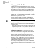
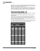
The Table
Venturi Table Statement Example
shows an example of active values in a
Venturi table statement after the Venturi Air Valves have been calibrated (note reverse
acting exhaust voltage). Table statement values will vary per system.
Venturi Table Statement Example (active values).
Supply
Venturi Air Valve
General exhaust
Venturi Air Valve
cfm
volts
cfm
volts
0
a)
0
a)
0
a)
10
a)
210
0.25
180
5.48
213
0.83
216
5.08
224
1.53
244
4.68
268
2.93
340
3.88
313
3.63
368
3.48
373
4.57
452
2.98
382
5.04
476
2.73
418
5.51
504
2.48
521
6.46
572
1.98
531
6.93
604
1.73
598
7.4
618
1.48
777
8.34
712
0.98
861
8.81
760
0.73
980
9.28
800
0.48
1200
10
904
0