
Application

Sequence of Operation
Venturi Table Evaluation and Editing (Mode 1, 3)
25
Siemens Industry, Inc.
Application Note, App 2928
140-1302
2015-07-07
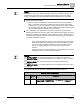
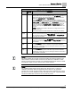
Venturi Air Valve Table Statement
V TABLE
PT
Description
32 - 46
This portion of the table (32 through 46) can be viewed but not edited
directly. When a point is selected (that is, when
V TABLE PT is set to a
value 32 through 46), the corresponding flow and voltage values are
displayed in
TABLE FLOW and TABLE VOLTS.
Setting
V TABLE PT to 32 will result in the smallest readable flow and
associated voltage for the exhaust Venturi Air Valve to be displayed in
TABLE FLOW and TABLE VOLTS; setting V TABLE PT to 46 will result in
the maximum flow and associated voltage for the exhaust Venturi Air
Valve to be displayed in
TABLE FLOW and TABLE VOLTS. The in
between values (33 through 45) are for the range of flow between min
and max.
NOTE: The table swap will fail if valid flow and voltage values are not
entered in Point 46.
Table entries marked as failed display FAIL for both flow and voltage.
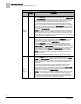
Inactive
Supply
61 – 76
This portion of the table can be viewed and edited. The user enters a
point (any value 61 through 76)
into V TABLE PT and the corresponding
cfm and voltage values display in
TABLE FLOW and TABLE VOLTS
where they can be edited.
Inactive
Exhaust
91 – 106
This portion of the table can be viewed and edited. By entering a point
(any value 91 through 106) into
V TABLE PT, the corresponding cfm and
voltage values display in
TABLE FLOW and TABLE VOLTS where they
can be edited.
Supply
Swap
120
Setting V TABLE PT to 120 instructs the controller to evaluate the values
in the inactive supply portion of the table using standard calibration
pass/fail logic. If they pass, they are exchanged with those in the active
supply portion of the table.
Exhaust
Swap
121
Setting V TABLE PT to 121 instructs the controller to evaluate the values
in the inactive exhaust portion of the table using standard calibration
pass/fail logic. If they pass, they are exchanged with those in the active
exhaust portion of the table.
NOTE:
The factory default value of SUP VLV STAT and GEX VLV STAT is NOTCAL. The
value of SUP VLV STAT or GEX VLV STAT is set whenever a calibration or table
transfer is performed as the last step of the calibration/table transfer. SUP VLV STAT
and GEX VLV STAT are never used for active control decisions.
NOTE:
The calibration table initially contains all zeros by default, that is, it contains no
calibration information. When the application detects all zeros, the application
operates, but runs with only PID control. If PID only control is satisfactory for a given
job, there is no need to populate the table. Should it be necessary, a populated table
can later be edited back to all zeroes to force PID only control.