
Application

Sequence of Operation
Temperature Control Loops
31
Siemens Industry, Inc.
Application Note, App 2928
140-1302
2015-07-07
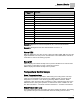
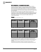
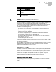
SENSOR SEL
Value *
Description
0
Analog Room Unit, 10K
1
Select Digital Room Unit (for temperature sensing and setpoint dial), 10K
2
Relative Humidity (RH) sensing, 10K
3
Digital Room Unit, RH, 10K
4
CO
2
sensing, 10K
5
Digital Room Unit, CO2, 10K
7
Digital Room Unit, RH, CO2, 10K
8
Analog Room Unit, 100K
9
Digital Room Unit, 100K
11
Digital Room Unit, RH, 100K
13
Digital Room Unit, CO2, 100K
15
Digital Room Unit, RH, CO2, 100k
16
(Not used)
Example 1: Digital Room Unit with temperature, RH, CO2 and 10K thermistor.
1+2+4+0 = 7
Example 2: Analog Room unit with 100K thermistor. 0+0+0+8 = 8
Room CO2
RM CO2 displays the CO
2
value in units of parts-per-million (PPM). RM CO2 (from the
digital 2200/2300 room units) can be used with PPCL in the PTEC/ATEC controller or
unbundled for control or monitoring purposes.
Room RH
RM RH displays the relative humidity value in percent. RM RH can be used for PPCL
in the PTEC or unbundled for control or monitoring purposes.
RM RH displays the relative humidity value in percent.
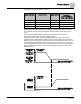
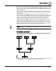
Temperature Control Loops
Room Temperature Loop
The room temperature loop operates in both heating and cooling modes. This loop
reads the room temperature control point, CTL TEMP, and then controls the room
temperature to the value of CTL STPT by generating TEMP LOOPOUT. TEMP
LOOPOUT is then used in the BTU calculations in order to determine the value of the
DISCH STPT and, during VAV operation, to determine the value of TEMP CTL VOL.
See
BTU Calculations – VAV Mode
and
BTU Calculations – Constant Volume Mode
.
Supply Temperature Loop
The supply temperature loop is a heating loop which operates at all times. The heating
loop generates the point VALVE CMD which drives the heating valve in order to