LCM-OAVS Room Pressurization with Slowacting Venturi Air Valves (One Exhaust, One Supply) and Hot Water Reheat Owner’s Manual 125-5083 125-5083 06/30/2015 Building Technologies
Table of Contents How To Use This Manual .................................................................................................. 4 Chapter 1 – Product Overview ......................................................................................... 6 Hardware Inputs .................................................................................................................. 7 Hardware Outputs ...................................................................................................
How To Use This Manual How To Use This Manual This manual is written for the owner and user of the LCM-OAVS Room Pressurization with Two Slow-acting Venturi Air Valves (One Supply, One Exhaust) and Hot Water Reheat. It is designed to help you become familiar with the Siemens Laboratory Controller Module and its applications. This section covers manual organization, manual conventions, symbols used in the manual, and other information that will help you use this manual.
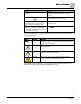
How To Use This Manual Convention Examples New terms appearing for the first time are The field panel continuously executes a useritalicized. defined set of instructions called the control program. This symbol signifies Notes. Notes provide additional information or helpful hints. Cross references to other information are For more information on creating flowcharts, see indicated with an arrow and the page Flowcharts [→92].
Chapter 1 – Product Overview Hardware Inputs Chapter 1 – Product Overview The LCM-OAVS Room Pressurization with Two Slow-acting Venturi Air Valves (One Supply, One Exhaust) and Hot Water Reheat is the Siemens Industry FLN controller used in pressure independent Variable Air Volume applications. It provides Direct Digital Control (DDC) for a number of applications. The controller can operate as an independent, stand-alone, DDC room controller or it can be networked with a field panel.
Chapter 1 – Product Overview Hardware Inputs Hardware Inputs Analog Air velocity sensor (one or two depending on setup) Application 2922 Application 2928 Fume hood controller input for FFM Application 2922 Application 2928 Room temperature sensor Application 2922 Application 2928 Discharge temperature sensor (10K (default) or 100K Ω software selectable thermistor) Application 2922 Application 2928 Digital Occupancy button (option on room temperature sensor) Application 2922 Application 2928 (Opti
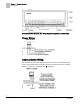
Chapter 1 – Product Overview Power Wiring Generic Controller I/O Layout. See Wiring Diagram for application specific details. Power Wiring Communication Wiring The controller connects to the field panel by means of a Floor Level Network (FLN) trunk. Communication wiring connects to the three screw terminals on the controller labeled “+” (positive), “-“ (negative), and “ ” (reference). 8 Siemens Industry, Inc.
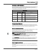
Chapter 1 – Product Overview Controller LED Indicators Controller LED Indicators The controller has eleven Light Emitting Diode (LED) indicators (see FigureLCM-OAVS Room Pressurization with Two Slow-acting Venturi Air Valves (One Supply, One Exhaust) and Hot Water Reheat). Table Controller LEDs lists the type, the abbreviation on the controller, and the indication of each LED. Controller LEDs.
Chapter 1 – Product Overview Actuators Discharge Temperature Sensor An optional discharge temperature sensor provides BTU compensation sensing to the controller. Actuators Actuators used with the LCM-OAVS Room Pressurization with Two Slow-acting Venturi Air Valves (One Supply, One Exhaust) and Hot Water Reheat include electronic damper motor. This actuator is controlled by the controller to position the damper or air valve.
Chapter 2 – Applications Basic Operation Chapter 2 – Applications Basic Operation The LCM-OAVS Room Pressurization with Two Slow-acting Venturi Air Valves (One Supply, One Exhaust) and Hot Water Reheat provides Direct Digital Control (DDC) technology for pressure independent Variable Air Volume (VAV) and Constant Volume (CV) laboratory room applications.
Chapter 2 – Applications Application 2928 LCM-OAVS Venturi Slow Speed, with BTU Compensation Application 2922 Control Drawing. Application 2928 LCM-OAVS Venturi Slow Speed, with BTU Compensation The controller controls pressurization, ventilation, and room temperature in a laboratory room served by one single-duct supply terminal with a reheat coil, one general exhaust terminal, and up to six fume hoods (multiple fume hood flow signals must be averaged using a Fume Hood Flow Module (FFM).
Chapter 2 – Applications Application 2928 LCM-OAVS Venturi Slow Speed, with BTU Compensation This application uses 0-10V output signals for control of slow Venturi Air Valves for both supply and general exhaust. The discharge temperature setpoint is reset in sequence with the VAV flow to control the room temperature using a BTU Compensation algorithm. The discharge temperature is then controlled using the reheat coil. The LCM controls pressure, ventilation, and temperature.
Chapter 2 – Applications Application 2997 Slave Mode Application 2997 Slave Mode Overview Application 2997 is the slave mode application for Laboratory Controller Module. Slave mode is the default application that opens when power is first applied to the controller. A controller in default state can also be used as a point extension device by unbundling spare I/O points at the field panel.
Chapter 3 – Point Database Chapter 3 – Point Database Chapter 3 presents a description of the LCM-OAVS Room Pressurization with Two Slow-acting Venturi Air Valves (One Supply, One Exhaust) and Hot Water Reheat point database, including point descriptors, point addresses, and a listing of applications in which each point is found. Address1 Application CTLR ADDRESS 01 All Identifies the controller on the LAN trunk. APPLICATION 02 All Identification number of the program running in the controller.
Chapter 3 – Point Database Address1 Application OCC BUTTON {19} All State of the push button switch on the thermostat. The momentary switch is only ON when the button is pushed. The value of this point provides no information on the occupancy state of the room. OCC.UNOCC {21} All Indicates the mode in which the controller is operating. Occupied temperature setpoints will be used in OCC mode. Unoccupied temperature setpoints will be used in UNOCC mode. This point is normally set by the field panel.
Chapter 3 – Point Database Address1 Application Description DIF ALM DBD 38 2922, 2928 Setting for the controller’s alarm; should be set lower than VOL DIF STPT to avoid losing pressurization completely. DIF ALM DEL 39 2922, 2928 Alarm delay point to prevent “nuisance alarms” on the flow difference. AVS FAIL MODE 40 2922, 2928 Indicates the desired position of the damper if the airflow sensor(s) fail. Valid input: CLOSED or OPEN.
Chapter 3 – Point Database Address1 Application {56} 2997 VALVE CLOSED 57 2922, 2928 Setup point. Tells the LCM what voltage fully closes the reheat valve. VALVE OPEN 58 2922, 2928 Setup point. Tells the LCM what voltage fully opens the reheat valve. {59} 2928 GEXDUCT AREA 60 2922, 2928 Internal cross-sectional area of the general exhaust duct where the flow sensor is installed.
Chapter 3 – Point Database Address1 Application DISCH I GAIN 81 2928 VOL DIFFRNC {83} 2922, 2928 The difference between measured airflow into the room, and measured airflow out. Equal to Point 53 through Point 69). AI 5 {84} 2922, 2997 Spare Analog input, 10K Ω (default) or 100K software selectable thermistor. DISCH TEMP {84} 2928 GEX FLO STPT {85} 2922, 2928 The desired value of the general exhaust.
Chapter 3 – Point Database Address1 Application MODHTG FLO 106 2922, 2928 The minimum flow in feet per minute needed for safety purposes when using electric reheat. DO DIR.REV 107 All Reverses the output state for selected non-motor digital outputs. {108} All Room humidity when room unit is provided with humidity sensing. FAIL TIME 109 2922, 2928 Indicates when the air volume is too far away from setpoint for too long.
Chapter 4 – Basic Service and Maintenance Basic Service Information Chapter 4 – Basic Service and Maintenance This chapter describes corrective measures you can take should you encounter a problem when using a Laboratory Controller Module. You are not required to do any controller troubleshooting. You may want to contact your local Siemens Industry representative if a problem occurs or you have any questions about the controller.
Glossary Glossary This glossary contains the collected terms and acronyms that are used in Siemens BACnet PTEC and TEC Controllers. For definitions of point database descriptors, see Chapter 3 - Point Database, in this manual. airflow Rate at which a volume of air moves through a duct. Usually expressed in cubic feet per minute (cfm) or liters per second (lps). algorithm Mathematical formula and control logic that uses varying inputs to calculate an output value. AVS Air Velocity Sensor.
Glossary Demand Control Ventilation A control algorithm that provides for the control or reduction of outdoor air intake below design rates when the actual occupancy of spaces served by the system is at less than design occupancy. DCV Demand Control Ventilation. DDC Direct Digital Control. Direct digital control The automated control of a condition or process by a digital device (computer). DO Digital Output. Physical output point that sends a two-state signal (ON/OFF, OPEN/CLOSED, YES/NO).
Glossary HMI Human Machine Interface. Terminal and its interface program that allows you to communicate with a field panel or equipment controller. Occupancy sensor A control device that detects presence of people in a space by using infrared or ultrasonic technology. Occupancy sensors are used to save energy by controlling lighting and temperature and, along with CO2 sensors, to provide control input of demand control ventilation (DCV) algorithms.
Glossary UI Universal Input. Can be used as an AI or DI. An AI input is a point receiving a signal that represents a condition that has more than two states. A DI input is a physical input point that receives a two-state signal. unbundle Term used to describe the entering of a point that resides in a controller's database into the field panel's database so that it can be monitored and controlled from the field panel. VAV Variable air volume.
Index Index A L actuators, 10 damper actuator, 10 valve actuator, 10 algorithm, 22 LED, 9 loopout, 23 B basic operation, 11 basic service information, 21 C centralized control, 22 Chilled Beam, 22 CO2, 22 control loop, 22 controller Terminal Box (VAV) Controller, 6 Terminal Equipment Controller, 6 CV, 22 M mounting bracket, 6 O override switch, 24, 24 P PID, 24 point database overview, 15 preventive maintenance, 21 R RTS, 24 S DCV, 23 DDC, 23 Demand Control Ventilation, 23 Direct digital control
Issued by Siemens Industry, Inc. Building Technologies Division 1000 Deerfield Pkwy Buffalo Grove IL 60089 Tel. +1 847-215-1000 Document ID 125-5083 Edition 06/30/2015 © Siemens Industry, Inc., 2015 Technical specifications and availability subject to change without notice.