
Operating Instructions

Chapter 3 – Point Database
19
Siemens Industry, Inc.
Owner's Manual
125-5083
06/30/2015
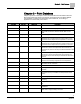
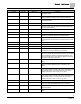
Descriptor
Address
1
Application
Description
DISCH I GAIN
81
2928
The integral feedback gain used to tune the discharge
temperature control.
VOL DIFFRNC
{83}
2922, 2928
The difference between measured airflow into the room, and
measured airflow out. Equal to Point 53 through Point 69).
AI 5
{84}
2922, 2997
Spare Analog input, 10K Ω (default) or 100K software
selectable thermistor.
DISCH TEMP
{84}
2928
Discharge temp sensor input.
GEX FLO STPT
{85}
2922, 2928
The desired value of the general exhaust. The controller
selects the lowest value that will lead to adequate supply flow,
and correct pressurization.
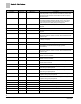
FAIL LIMIT
86
2922, 2928
Indicates when the air volume is too far away from setpoint.
CAL VENTURI
{87}
2922, 2928
Initiates and displays the initiation status of Venturi calibration.
VOL DIF STPT
{88}
2922, 2928
The desired value for the flow difference. This value can be
selected and adjusted to achieve room pressurization.
OTHER EXH
{89}
2922, 2928
The value of any exhaust airflows not connected to the LCM.
Must be entered to the controller to account for flows it cannot
detect.
OCV ALM LVL
90
2922, 2928
Ventilation alarm level in occupied mode.
UCV ALM LVL
91
2922, 2928
Ventilation alarm level in unoccupied mode.
VENT ALM
{92}
2922, 2928
Alarm point indicates inadequate air change rate.
SUP FLO STPT
{93}
2922, 2928
The desired value of the supply flow, chosen by the controller,
to achieve the correct flow difference for the room.
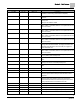
CAL AIR
{94}
All
YES commands the controller to go through calibration
sequence for the air velocity transducers. YES is also displayed
when the calibration sequence is started automatically. CAL
AIR automatically returns to NO after the calibration sequence
is completed. Valid input: YES or NO.
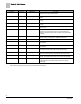
CAL SETUP
95
All
The configuration setup code for the calibration sequence
options.
CAL TIMER
96
All
Time interval, in hours, between the calibration sequence
initiations if a timed calibration option is selected in CAL
SETUP.
SUPDUCT AREA
97
2922, 2928
Area, in square feet (square meters), of the supply duct where
the air velocity sensor is located. This value is calculated by the
field panel depending on duct shape and size. It is used in
calculating all points in units of cfm, CF, lps, and L.
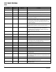
DUCT AREA 1
97
2997
Area, in square feet (square meters), of the supply duct where
the air velocity sensor is located. This value is calculated by the
field panel depending on duct shape and size. It is used in
calculating all points in units of cfm, CF, lps, and L.
LOOP TIME
98
2922, 2928
The time, in seconds, between control loop calculations.
ERROR STATUS
{99}
All
The status code indicating any errors detected during controller
power up. A status of 0 indicates there are no problems.
SENSOR SEL
104
All
Room unit configuration point and thermistor type selection,
values are additive.
VENTURI ACT
105
2922, 2928
Setup point. Indicates NOPEN or NCLOSE for Venturi Air
Valves.