
Operating Instructions

Chapter 3 – Point Database
20
Siemens Industry, Inc.
Owner's Manual
125-5083
06/30/2015
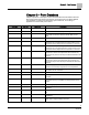
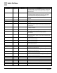
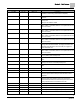
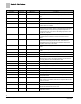
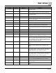
Descriptor
Address
1
Application
Description
MODHTG FLO
106
2922, 2928
The minimum flow in feet per minute needed for safety
purposes when using electric reheat.
DO DIR.REV
107
All
Reverses the output state for selected non-motor digital
outputs.
RM RH
{108}
All
Room humidity when room unit is provided with humidity
sensing.
FAIL TIME
109
2922, 2928
Indicates when the air volume is too far away from setpoint for
too long.
MINHOODVOLTS
117
2922, 2928
Minimum voltage value for fume hood input range (typically
0.0V or 1.0V.
RM CO2
{118}
All
A point can be unbundled in the controller for monitoring
purposes. This point may be used in a control strategy as
occupancy increases (CO2 levels increase) in the room being
controlled.
TABLE VOLTS
{119}
2922, 2928
Editable table statement point allowing low flow functionality;
actuator voltage corresponds to TABLE FLOW value.
VTABLE PT
{120}
2922, 2928
Venturi table statement, only point that can be edited.
HI LIMIT
121
2922, 2928
Used in the determination of when the flow PID will “coast” if
near setpoint.
LO LIMIT
122
2922, 2928
Used in the determination of when the flow PID will “coast” if
near setpoint.
S OPEN LOOP
123
2922, 2928
YES commands the controller to operate in the supply in Open
Loop mode. No PID control will be used in this mode.
G OPEN LOOP
124
2922, 2928
YES commands the controller to operate in the exhaust in
Open Loop mode. No PID control will be used in this mode.
SUP MAX RATE
125
2922, 2928
The point is used to effectively limit the speed of the Supply
actuator. The default value of zero turns off this functionality.
GEX MAX RATE
126
2922, 2928
The point is used to effectively limit the speed of the General
Exhaust actuator. The default value of zero turns off this
functionality.
1)
Points not listed are not used in this application.
2)
Point numbers that appear in brackets { } may be unbundled at the field panel.