Fume Hood Controller Vertical Sash Configuration with Damper or Venturi Valve, Application 2941 & 2942 Application Note Building Technologies 140-1319 2015-11-04 Restricted
Table of Contents Overview ............................................................................................................................. 4 Hardware Inputs .................................................................................................................. 6 Hardware Outputs ................................................................................................................ 7 Ordering Notes .............................................................................
Overview Hardware Inputs Overview Application 2941 and Application 2942 are designed for use with a wide range of fume hood sash configurations connected to a manifold fume hood exhaust system.
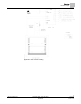
Overview Hardware Inputs Application 2941 Control Drawing. 5 Siemens Industry, Inc.
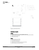
Overview Hardware Inputs Application 2942 Control Drawing. Hardware Inputs Analog Air velocity sensor(s) – (2nd sensor available for field use) (Optional) Differential pressure transmitter/Linear Flow input (Vortex Shedder) (Optional) External face area Vertical sash sensor(s) Digital Operator Display Panel (ODP) ATTN.UNATTN (through DI 2) OCC.UNOCC (through DI 2) (Optional) OCC Face Velocity Setpoint (through ODP) Remote Emergency Purge (through DI 6) 6 Siemens Industry, Inc.
Overview Hardware Outputs Hardware Outputs Analog Operator Display Panel (ODP) AO2 (flow signal, 1 to 10 Vdc) AO3 Analog Actuation Digital Autozero Solenoid in Offboard Air Module (DO8) (Optional) Alarm (DO 7) (Optional) OFF Mode (DO 6) Exhaust damper (DO 1 and DO 2, Floating Control Actuation) Ordering Notes 570-00700N Fume Hood Controller Universal Sash Configuration with Damper or Venturi Air Valve – Application 2941 and 2942 570-00700E Fume Hood Controller Universal Sash Configurat
Sequence of Operation Average Face Velocity Control Sequence of Operation The following paragraphs present the sequence of operation for Fume Hood Controller Application 2941 and Application 2942: Vertical Sash Configuration Fume Hood with Damper or Venturi Air Valve. Average Face Velocity Control In face velocity mode, the Fume Hood Controller maintains the average face velocity at the face velocity setpoint, FVEL STPT.
Sequence of Operation AVS Calibration If the face velocity setpoint is overridden by the system or the controller is in Emergency/General Failure this function does not work. The controller will remember the current occupied face velocity setpoint even after changing from unoccupied back to occupied. Air Velocity Sensing Primary sensing of the exhaust airflow is through the OAVS. Optionally, AI3 may be used to input a Differential pressure transmitter or a Linear Flow input signal.
Sequence of Operation Control Loop - Damper Application AO2 DEADBAND defaults to 5.2%. If EXH STPT is 1000 cfm, AO2 FLOW SIG = EXH STPT if the actual flow is between 948 and 1052 cfm (these values are approximate and will vary based on duct area). If the actual flow is outside these values AO2 FLOW SIG = EXH VOL. For stable pressure reading, lower the AO2 DEADBAND. For unstable pressure readings, raise the AO2 DEADBAND until the output signal stabilizes. AO2 DEADBAND can be set from 0 to 102% in 0.
Sequence of Operation Venturi Application The controller sends a separate signal to each of the two inputs that reside on the damper actuator. For values of 100% to 0%, the controller sends a decreasing percentage of the full signal length to the retract input. For values of 0% to -100%, the controller sends an increasing percentage of the full signal to the extend input. Venturi Application Venturi Operational Modes Mode 1 – Operates with both a PID loop and a Venturi table.
Sequence of Operation Venturi Application Venturi Table Statement Example (active values). Exhaust Venturi Air Valve cfm volts 0 a) 10 a) 180 5.48 216 5.08 244 4.68 340 3.88 368 3.48 452 2.98 476 2.73 504 2.48 572 1.98 604 1.73 618 1.48 712 0.98 760 0.73 800 0.48 904 0 NOTE: The first pair (or “point”) of flow/voltage values in the table statement is the low flow point.
Sequence of Operation Venturi Application Venturi Airflow @ 350 fpm. Valve Size in Inches cfm 5 48 6 69 8 122 10 191 12 275 Dual 10 380 Dual 12 550 Triple 12 825 During calibration, 15 voltage/flow values are automatically generated (the first pair of voltage/flow values—the low flow point—is not generated; it must be set manually). The Venturi Valve actuator is then fed the voltages and the application reads the resulting airflows.
Sequence of Operation Venturi Application Venturi Table Evaluation and Editing (Mode 1, 3) A Venturi Air Valve table statement consists of two sets of voltage/flow values—one set is active and the other inactive. When you run the calibration, the first thing that happens is that the inactive table values are filled in with new values generated by the calibration. Then the application checks these new values to make sure they are good.
Sequence of Operation Venturi Application ⇨ If your proposed values are good, then the swap is made and the edited values are accepted into the active portion of the table. EXH VLV STAT is set to CAL OK for exhaust calibration and control of the Venturi Air Valve resumes. ⇨ However, if either point is set to NOTCAL, you must gather and view the voltage/flow values to see where the problem lies. The following table lists all values for V TABLE PT and describes their use.
Sequence of Operation Venturi Application NOTE: The calibration table initially contains all zeros by default, that is, it contains no calibration information. When the application detects all zeros, the application operates, but runs with only PID control. If PID only control is satisfactory for a given job, there is no need to populate the table. If necessary, a populated table can later be edited back to all zeroes to force PID only control.
Sequence of Operation Venturi Application When operating open loop, there is no flow sensor for use in the calibration sequence. Instead, the Venturi table values are directly input by the user. If the Venturi Valve has end points for calibration such as 1200 cfm at end voltage, and an implied lower range of 0 cfm at its other end of the voltage range, you should enter this information into Point 16, as shown in Example 1 and 2 below. Point Flow Volt 1 0 10.0 2 0 10.0 15 0 10.0 16 1200 0.
Sequence of Operation Minimum Exhaust Mode You can also manually populate the table with additional values as shown in Example 3 below. In this case, the table becomes indistinguishable from a table generated via the calibration process. Point Flow Volt 1 300 10 2 340 7.0 3 390 5.8 4 521 4.9 5 531 4.1 6 598 3.8 7 691 3.5 8 798 3.2 9 1200 3.
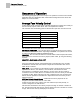
Sequence of Operation Maximum Exhaust Mode Exhaust Control Schedule. Maximum Exhaust Mode If, as the open sash area is increased, the calculated exhaust airflow setpoint, EXH STPT rises above the maximum airflow specified in EXH MAX, then EXH STPT is set equal to EXH MAX. Under this maximum flow condition, the ODP displays the average face velocity that will drop as the open sash area is further increased.
Sequence of Operation Alarm Limits Warning and Alarm Schedule. Alarm Limits The Fume Hood Controller contains high and low flow alarm limits, HI ALM LMT and LOW ALM LMT, respectively. The alarm limits are defined as a percentage of the controller setpoint; therefore, the alarm limits apply to EXH STPT during normal control. For either of the alarms to become active, the alarm condition must be maintained for the time specified in ALARM TIME.
Sequence of Operation Sash Area Alarms Sash Area Alarms NOTE: Sash alarms are set to be OFF by default and are not required on most jobs. Enabling sash alarms requires training for the operators. Sash area alarms alert you when the sash area is above set limits. There are limits for both attended and unattended modes of operation. The controller uses the following points to perform this function: DI2, ATTN.UNATTN, SASH TONE, UN ALRT AREA, AT ALRT AREA, OPEN TIME, and SASH OP ALRT. ATTN.
Sequence of Operation Start-up/Decommission Mode 3. After EMER TIMER has timed out, the Fume Hood Controller controls the flow at the flow setpoint, EXH STPT, multiplied by the emergency set point percentage, EMER STPT. 4. When the Emergency Purge button is pressed a second time, the Fume Hood Controller returns to normal operation for the current conditions. Emergency Purge Schedule. NOTE: Norm = Normal operation in which control is at the EXH STPT.
Sequence of Operation Fail Mode The modes are described as an enumerated point: STARTUP MODE Mode Description 0 Normal 1 Decommission The controller is fully functional, except the flow setpoint is set to 0, alarming is limited and the ODP displays “Out of service” and “OFF”. If the sash is opened, control is returned and you are notified that the hood is “Out of service”.
Sequence of Operation Wiring Diagrams Face Velocity – If the Face Velocity falls out of the safe range of operation, the LOW ALM or HIGH ALM turns ON and alarms are displayed on the ODP indicating unsafe operating conditions. Wiring Diagrams Offboard Air Module Wiring. CAUTION The FHC-OAVS has two terminal blocks with terminations numbered identically (terminations 1 through 16). DO NOT mix these up with each other. If the FHC-OAVS is not connected as shown, it is not resistant to electrical surges.
Sequence of Operation Wiring Diagrams Wiring for AI5: Sash Sensor 1. Wiring for AI4: Sash Sensor 2. WARNING The application cannot detect a broken wire to the analog input for the second sash. An external sash aggregating device should be used to calculate the face area for all fume hoods with more than one sash. 25 Siemens Industry, Inc.
Sequence of Operation Wiring Diagrams WARNING Must use external 10 Vdc power supply. Do not power AI from an onboard AO that is forced to 10 volts. Wiring for AI with a 4 to 20 mA Sensor. CAUTION Each 4-20 mA sensor requires a SEPARATE dedicated power limited 24 Vdc power supply. DO NOT use the same transformer to power both the sensor and the controller.
Sequence of Operation Wiring Diagrams NOTE: The controller’s DOs control 24 Vac loads only. The maximum rating is 12 VA for each DO. An external interposing relay is required for any of the following: • VA requirements higher than the maximum • 110 or 220 Vac requirements • DC power requirements • Separate transformers used to power the load (for example, part number 540-147, Terminal Equipment Controller Relay Module) 27 Siemens Industry, Inc.
Sequence of Operation Wiring Diagrams Application 2941 Wiring Diagram. 28 Siemens Industry, Inc.
Sequence of Operation Wiring Diagrams Application 2942 Wiring Diagram. 29 Siemens Industry, Inc.
Point Database Application 2941 Point Database Application 2941 Point Number a), Descriptor Factory Default (SI Units) c) Eng Units (SI Units) c) Slope (SI Units) c) Intercept (SI Units) c) On Text Off Text 1 CTLR ADDRESS 99 -- 1 0 -- -- 2 APPLICATION 2900 -- 1 0 -- -- {04} FACE VEL 0 (0.0) FPM ( MPS) 1 (0.
Point Database Application 2941 Point Number a), Descriptor Factory Default (SI Units) c) Eng Units (SI Units) c) Slope (SI Units) c) Intercept (SI Units) c) On Text Off Text 34 TRANS RANGE 0.0 (0.0) IN H2O (K PA) 0.0001 (0.000025) 0 -- -- 35 LINEAR FL RG 0 (0.0) CFM ( LPS) 4 (1.8876) 0 -- -- {36} AVS2 PRESS 0.0 (0.0) IN H2O (K PA) 0.0001 (0.000025) 0 -- -- {37} DI 2 OFF -- -- -- ON OFF {38} DI 6 OFF -- -- -- ON OFF {39} AO 1 0 VOLTS 0.
Point Database Application 2941 Point Number a), Descriptor b) Factory Default (SI Units) c) Eng Units (SI Units) c) Slope (SI Units) c) Intercept (SI Units) c) On Text Off Text (CM) 66 VERT WIDTH2 0.0 (0.0) INCHES (CM) 0.5 (1.27) 0 -- -- 67 VSASH HGHT1 0.0 (0.0) INCHES (CM) 0.5 (1.27) 0 -- -- 68 VSASH HGHT2 0.0 (0.0) INCHES (CM) 0.5 (1.27) 0 -- -- 69 TRACK HEIGHT 0.0 (0.0) INCHES (CM) 0.5 (1.27) 0 -- -- 70 BYPASS HGHT 0.0 (0.0) INCHES (CM) 0.5 (1.
Point Database Application 2941 Point Number a), Descriptor Factory Default (SI Units) c) Eng Units (SI Units) c) Slope (SI Units) c) Intercept (SI Units) c) On Text Off Text {97} AVS1 PRESS 0.0 (0.0) IN H2O (K PA) 0.0001 (0.000025) 0 -- -- 98 LOOP TIME 0.1 SEC 0.1 0 -- -- {99} ERROR STATUS 0 -- 1 0 -- -- 106 DISPLAY WT 100 PCT 0.4 0 -- -- 107 DISPLAY RES 5 (0.0254) FPM ( MPS) 1 (0.
Point Database Application 2942 Point Database Application 2942 Point Number a), Descriptor Factory Default (SI Units) c) Eng Units (SI Units) c) Slope (SI Units) c) Intercept (SI Units) c) On Text Off Text 1 CTLR ADDRESS 99 -- 1 0 -- -- 2 APPLICATION 2900 -- 1 0 -- -- {04} FACE VEL 0 (0.0) FPM ( MPS) 1 (0.
Point Database Application 2942 Point Number a), Descriptor Factory Default (SI Units) c) Eng Units (SI Units) c) Slope (SI Units) c) Intercept (SI Units) c) On Text Off Text 34 TRANS RANGE 0.0 (0.0) IN H2O (K PA) 0.0001 (0.000025) 0 -- -- 35 LINEAR FL RG 0 (0.0) CFM ( LPS) 4 (1.8876) 0 -- -- {36} AVS2 PRESS 0.0 (0.0) IN H2O (K PA) 0.0001 (0.000025) 0 -- -- {37} DI 2 OFF -- -- -- ON OFF {38} DI 6 OFF -- -- -- ON OFF {39} AO 1 0 VOLTS 0.
Point Database Application 2942 Point Number a), Descriptor Factory Default (SI Units) c) Eng Units (SI Units) c) Slope (SI Units) c) Intercept (SI Units) c) On Text Off Text 66 VERT WIDTH2 0.0 (0.0) INCHES (CM) 0.5 (1.27) 0 -- -- 67 VSASH HGHT1 0.0 (0.0) INCHES (CM) 0.5 (1.27) 0 -- -- 68 VSASH HGHT2 0.0 (0.0) INCHES (CM) 0.5 (1.27) 0 -- -- 69 TRACK HEIGHT 0.0 (0.0) INCHES (CM) 0.5 (1.27) 0 -- -- 70 BYPASS HGHT 0.0 (0.0) INCHES (CM) 0.5 (1.
Point Database Application 2942 Point Number a), Descriptor Factory Default (SI Units) c) Eng Units (SI Units) c) Slope (SI Units) c) Intercept (SI Units) c) On Text Off Text 96 CAL TIMER 12 HRS 1 0 -- -- {97} AVS1 PRESS 0.0 (0.0) IN H2O (K PA) 0.0001 (0.000025) 0 -- -- 98 LOOP TIME 0.1 SEC 0.1 0 -- -- {99} ERROR STATUS 0 -- 1 0 -- -- 106 DISPLAY WT 100 PCT 0.4 0 -- -- 107 DISPLAY RES 5 (0.0254) FPM ( MPS) 1 (0.
Point Database Application 2900 Point Database Application 2900 Point Number a), Descriptor Factory Default (SI Units) c) Eng Units (SI Units) c) Slope (SI Units) c) Intercept (SI Units) c) On Text Off Text 1 CTLR ADDRESS 99 -- 1 0 -- -- 2 APPLICATION 2900 -- 1 0 -- -- {36} AVS2 PRESS 0.0 (0.0) IN H2O (K PA) 0.0001 (0.000025) 0 -- -- {37} DI 2 OFF -- -- -- ON OFF {38} DI 6 OFF -- -- -- ON OFF {39} AO 1 0 VOLTS 0.01 0 -- -- {40} AO 3 0 VOLTS 0.
Issued by Siemens Industry, Inc. Building Technologies Division 1000 Deerfield Pkwy Buffalo Grove IL 60089 Tel. +1 847-215-1000 Document ID 140-1319 Edition 2015-11-04 © Siemens Industry, Inc., 2015 Technical specifications and availability subject to change without notice.