
Application
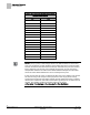
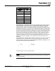
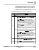
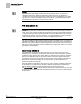
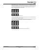
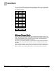
Table Of Contents
- Overview
- Sequence of Operation
- Average Face Velocity Control
- AVS Calibration
- AO2 Flow Signal
- Control Loop - Damper Application
- Venturi Application
- Minimum Exhaust Mode
- Maximum Exhaust Mode
- Warning Limits
- Alarm Limits
- Alarm Output
- Horn Disable
- Sash Area Alarms
- Table Access Feature
- Emergency Mode
- Start-up/Decommission Mode
- Fail Mode
- Wiring Diagrams
- Point Database Application 2941
- Point Database Application 2942
- Point Database Application 2900

Sequence of Operation
Venturi Application
11
Siemens Industry, Inc. Application Note, Apps 2941/2942 140-1319
Restricted 2015-11-04
The controller sends a separate signal to each of the two inputs that reside on the
damper actuator. For values of 100% to 0%, the controller sends a decreasing
percentage of the full signal length to the retract input. For values of 0% to -100%, the
controller sends an increasing percentage of the full signal to the extend input.
Venturi Application
Venturi Operational Modes
Mode 1 – Operates with both a PID loop and a Venturi table.
This mode provides the best control and is the most commonly used mode for these
applications. In this mode, the embedded Venturi table statements work together with a
PID feedback loop to operate the Venturi air valve so that the measured air velocity is
maintained at setpoint. The following sections describe this mode.
Mode 2 - Operates with a PID loop, but no Venturi table.
In this mode, the controller operates with PID control based on a flow sensor input, but
the Venturi table is not used. See the
PID Only Mode
section for specific information
on this mode.
Mode 3 - Operates with Venturi table, but no PID loop
In this mode, the controller operates open loop (without a flow sensor). There is no PID
control. Positioning of the actuator is based solely on a Venturi table consisting of
command voltages and their resultant corresponding airflows. See the
Open Loop
Operation (Mode 3)
section for specific information on configuring the application for
open loop control.
Venturi Air Valve Calibration (Mode 1, 3)
Calibration of the Venturi Air Valve(s) must be performed at least once during start-up
to determine the relationship between airflow and the voltage curve of the actuator.
Prerequisites for calibrating Venturi Air Valves:
Fully operational exhaust airflow systems.
Exhaust Air Velocity Sensor is calibrated and working normally (EXH VOL cannot
be Failed).
If operating without an Air Velocity Sensor, see the
Open Loop (Mode 3)
section.
Table Access Feature (Mode 1, 3)
The table contains 16 pairs of “active” voltage/flow values, and 16 pairs of “inactive”
voltage/flow values.
The active values are used to operate the Venturi Air Valve at desired airflows. For
example, when the controller is given a flow setpoint value of 500 cfm, it goes to the
active portion of the table statement and looks up what the voltage output to the
actuator should be in order to achieve 500 cfm. The inactive values are used to edit the
active values as explained later in this section.
Table
Venturi Table Statement Example
shows an example of active values in a
Venturi table statement after the Venturi Air Valves have been calibrated (note reverse
acting exhaust voltage). Table statement values will vary per system.