
Application
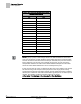
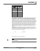
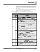
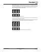
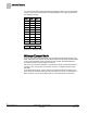
Table Of Contents
- Overview
- Sequence of Operation
- Average Face Velocity Control
- AVS Calibration
- AO2 Flow Signal
- Control Loop - Damper Application
- Venturi Application
- Minimum Exhaust Mode
- Maximum Exhaust Mode
- Warning Limits
- Alarm Limits
- Alarm Output
- Horn Disable
- Sash Area Alarms
- Table Access Feature
- Emergency Mode
- Start-up/Decommission Mode
- Fail Mode
- Wiring Diagrams
- Point Database Application 2941
- Point Database Application 2942
- Point Database Application 2900

Sequence of Operation
Venturi Application
12
Siemens Industry, Inc. Application Note, Apps 2941/2942 140-1319
Restricted 2015-11-04
Venturi Table Statement Example (active values).
Exhaust Venturi Air Valve
cfm
volts
0
a)
10
a)
180 5.48
216 5.08
244 4.68
340 3.88
368 3.48
452 2.98
476 2.73
504 2.48
572 1.98
604 1.73
618 1.48
712 0.98
760 0.73
800 0.48
904 0
NOTE:
The first pair (or “point”) of flow/voltage values in the table statement is the low flow
point. It is provided for low flow situations where airflow through the Venturi Air Valve
must be controlled at velocities less than 350 fpm. Otherwise, this point can be left at
factory default of 0 cfm and 0V (10V if exhaust) and ignored, as is the case in the
example table statement in Table
Venturi Table Statement Example
. See the Table
Venturi Air Valve Table Statement
for how to manually set this point.
If there is a low flow cfm value, it is taken from either the room schedule or the Venturi
Air Valve housing. Cubic feet per minute (cfm) flows in this range (where velocity
equals less than 350 fpm) and related voltages must be determined and/or confirmed
with help from a balancer. See Table
Venturi Airflow @ 350 fpm
for cfm flows equal to
350 fpm. The following equation associates airflow to air velocity:
Airflow (cfm) = Velocity (fpm) × Duct Area (sq ft) × Flow Coefficient.