
Application
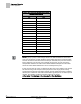
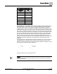
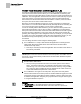
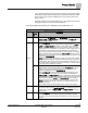
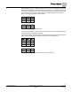
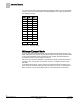
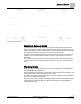
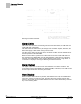
Table Of Contents
- Overview
- Sequence of Operation
- Average Face Velocity Control
- AVS Calibration
- AO2 Flow Signal
- Control Loop - Damper Application
- Venturi Application
- Minimum Exhaust Mode
- Maximum Exhaust Mode
- Warning Limits
- Alarm Limits
- Alarm Output
- Horn Disable
- Sash Area Alarms
- Table Access Feature
- Emergency Mode
- Start-up/Decommission Mode
- Fail Mode
- Wiring Diagrams
- Point Database Application 2941
- Point Database Application 2942
- Point Database Application 2900

Sequence of Operation
Venturi Application
13
Siemens Industry, Inc. Application Note, Apps 2941/2942 140-1319
Restricted 2015-11-04
Venturi Airflow @ 350 fpm.
Valve Size in
Inches
cfm
5 48
6 69
8 122
10 191
12 275
Dual 10 380
Dual 12 550
Triple 12 825
During calibration, 15 voltage/flow values are automatically generated (the first pair of
voltage/flow values—the low flow point—is not generated; it must be set manually).
The Venturi Valve actuator is then fed the voltages and the application reads the
resulting airflows. At the end of calibration, the airflow readings are analyzed and the
calibration is either given a CAL OK or a NOT CAL (EXH VLV STAT). To obtain a CAL
OK, at least 5 of the airflow readings must increment correctly (the points in the table
increase as the voltage increases). For example, if one point on the voltage/flow curve
shows 5V and 500 cfm and the next point shows 6V and 450 cfm, the second point
(6V, 450 cfm) would fail. But 6V at 550 cfm would pass. (This example assumes the
actuator is direct acting, where more volts equal more flow. Exhaust devices are
usually reverse acting and have an inverse voltage/flow relationship.) Too many failed
airflow points along the voltage/flow curve will result in a NOT CAL status for the
calibration.
This application has a table statement edit feature that allows you to view and edit the
voltage/flow values in the table. This is useful for fine tuning the air valve to meet
precise room flow setpoints and for diagnosing/editing problematic voltage/flow curves
(see Table
Venturi Air Valve Table Statement
).
Problematic Venturi Air Valve Voltage/Flow Curves.
NOTE:
Bouncy flow means that airflow through the air valve’s flow orifice is too turbulent to
be read consistently.