
Application
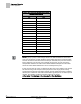
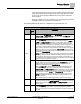
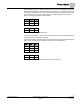
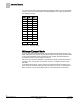
Table Of Contents
- Overview
- Sequence of Operation
- Average Face Velocity Control
- AVS Calibration
- AO2 Flow Signal
- Control Loop - Damper Application
- Venturi Application
- Minimum Exhaust Mode
- Maximum Exhaust Mode
- Warning Limits
- Alarm Limits
- Alarm Output
- Horn Disable
- Sash Area Alarms
- Table Access Feature
- Emergency Mode
- Start-up/Decommission Mode
- Fail Mode
- Wiring Diagrams
- Point Database Application 2941
- Point Database Application 2942
- Point Database Application 2900

Sequence of Operation
Venturi Application
14
Siemens Industry, Inc. Application Note, Apps 2941/2942 140-1319
Restricted 2015-11-04
Venturi Table Evaluation and Editing (Mode 1, 3)
A Venturi Air Valve table statement consists of two sets of voltage/flow values—one
set is active and the other inactive. When you run the calibration, the first thing that
happens is that the inactive table values are filled in with new values generated by the
calibration. Then the application checks these new values to make sure they are good.
If they pass (that is, if enough increment correctly), these new values become the
active values, and the old active values become inactive. However, if the new values
don’t pass, then the old active values remain active.
Running a successful calibration sequence is one way of changing or updating the
active values. You can also edit the table manually. Normally this is not necessary, but
if you are having flow control problems you may need to edit the table.
In order to manually edit the table statement, you must first know which points in the
active table need adjusting. This is done by setting V TABLE PT
to the appropriate
active point values found in Table
Venturi Air Valve Table Statement
in order to gather
and view the active voltage/flow curve for the Venturi Air Valve and its actuator. By
gathering and analyzing the active voltage/flow values (for example, you can plot them
on a graph as in Figure
Problematic Venturi Air Valve Voltage/Flow Curves
), you can
decide which one(s) need adjusting. The flow curve should be smooth and
incremental.
You can change the active values using the following steps:
1. Set V TABLE PT to a “swap” value that tells the application to exchange active
table values with inactive table values (see Table
Venturi Air Valve Table
Statement
for swap value).
This step is necessary because the application does not allow active values to
be manually overridden.
NOTE:
An exception to this rule is the first element in the active portion of the table—the low
flow point—can be edited directly. Table
Venturi Air Valve Table Statement
explains
this in more detail.
2. Edit the inactive table values.
Since you have just switched the active and inactive portions of the table in
Step 1, the inactive values are now identical to what the active values were
moments ago. You can now edit these new inactive values by using V TABLE
PT to reference them in TABLE FLOW and TABLE VOLTS. Table
Venturi Air
Valve Table Statement
explains this in more detail.
3. Set V TABLE PT once again to the swap value. This places the newly edited
inactive values back into the active portion of the table statement (again, the active
and inactive portions of the table are simply swapped). However, before the swap
is finalized, the application analyzes your proposed values using the same logic as
in a regular calibration sequence.
NOTES:
1. If
FLOW COEF
is 0, the table edit feature uses a flow coefficient of 1.
2. If
DUCT AREA
is 0, the table edit feature uses a duct area of 1 square foot.