
Application
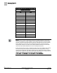
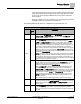
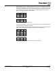
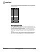
Table Of Contents
- Overview
- Sequence of Operation
- Average Face Velocity Control
- AVS Calibration
- AO2 Flow Signal
- Control Loop - Damper Application
- Venturi Application
- Minimum Exhaust Mode
- Maximum Exhaust Mode
- Warning Limits
- Alarm Limits
- Alarm Output
- Horn Disable
- Sash Area Alarms
- Table Access Feature
- Emergency Mode
- Start-up/Decommission Mode
- Fail Mode
- Wiring Diagrams
- Point Database Application 2941
- Point Database Application 2942
- Point Database Application 2900

Sequence of Operation
Venturi Application
16
Siemens Industry, Inc. Application Note, Apps 2941/2942 140-1319
Restricted 2015-11-04
NOTE:
The calibration table initially contains all zeros by default, that is, it contains no
calibration information. When the application detects all zeros, the application
operates, but runs with only PID control. If PID only control is satisfactory for a given
job, there is no need to populate the table. If necessary, a populated table can later
be edited back to all zeroes to force PID only control.
PID Only (Mode 2)
NOTE:
The default P gain value is intended for PID operation in conjunction with the Venturi
table. The P gain and Venturi table work together to provide an appropriate response
to setpoint changes. When operating without the Venturi table in PID Only mode, the
application is slower to respond. Therefore, you should adjust the P gain as needed
when operating in PID Only mode to ensure acceptable performance.
The Venturi calibration table initially contains all zeros by default, that is, it contains no
calibration information. When the application detects a zero flow for the sixteenth entry
(the table entry with the highest flow), the application does operate, but runs with only
PID control. If PID Only mode control is satisfactory for a given job; there is no need to
populate the Venturi tables.
Open Loop (Mode 3)
This application can operate in open loop mode. In open loop control, there is no
airflow sensor to provide an actual airflow measurement. Instead, operation is based
completely on the values in the Venturi table. For example, if the actuator’s setpoint is
600 cfm, the application will use the Venturi table to derive the voltage setting that
generates a flow of 600 cfm and then set the actuator to that voltage to generate the
desired flow. Assuming the table has accurate entries, the flow (if it were to be
measured) would be at setpoint.
Internally within the application, with open loop control, the flow is always assumed to
be at setpoint As a result there is virtually no difference between flow tracking and
setpoint tracking when the actuator being tracked is operating open loop.
Set OPEN LOOP to YES to indicate that the actuator is to operate open loop. This will
suppress the AVS failure indication that otherwise would occur when no airflow sensor
is connected.