
Application
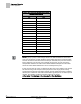
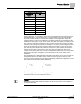
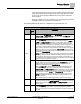
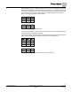
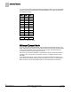
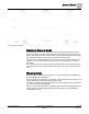
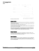
Table Of Contents
- Overview
- Sequence of Operation
- Average Face Velocity Control
- AVS Calibration
- AO2 Flow Signal
- Control Loop - Damper Application
- Venturi Application
- Minimum Exhaust Mode
- Maximum Exhaust Mode
- Warning Limits
- Alarm Limits
- Alarm Output
- Horn Disable
- Sash Area Alarms
- Table Access Feature
- Emergency Mode
- Start-up/Decommission Mode
- Fail Mode
- Wiring Diagrams
- Point Database Application 2941
- Point Database Application 2942
- Point Database Application 2900

Sequence of Operation
Venturi Application
17
Siemens Industry, Inc. Application Note, Apps 2941/2942 140-1319
Restricted 2015-11-04
When operating open loop, there is no flow sensor for use in the calibration sequence.
Instead, the Venturi table values are directly input by the user. If the Venturi Valve has
end points for calibration such as 1200 cfm at end voltage, and an implied lower range
of 0 cfm at its other end of the voltage range, you should enter this information into
Point 16, as shown in Example 1 and 2 below.
Point
Flow
Volt
1 0 10.0
2 0 10.0
15 0 10.0
16 1200 0.0
Example 1 - Table with CFM End Limits
It may not be necessary to enter 10.0 values since 10.0 values are initially in the table
by default when reverse acting is selected.
If specific information about the voltage at low flow is known, that would be entered into
point 1 which is reserved for information about low flow. See Example 2.
Point
Flow
Volt
1 300 7.0
2 0 10.0
3 0 10.0
15 0 10.0
16 1200 0.0
Example 2 - Table with Voltage End Limits and Low Flow Value