
Application
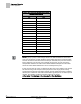
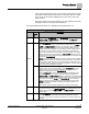
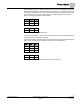
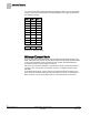
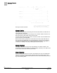
Table Of Contents
- Overview
- Sequence of Operation
- Average Face Velocity Control
- AVS Calibration
- AO2 Flow Signal
- Control Loop - Damper Application
- Venturi Application
- Minimum Exhaust Mode
- Maximum Exhaust Mode
- Warning Limits
- Alarm Limits
- Alarm Output
- Horn Disable
- Sash Area Alarms
- Table Access Feature
- Emergency Mode
- Start-up/Decommission Mode
- Fail Mode
- Wiring Diagrams
- Point Database Application 2941
- Point Database Application 2942
- Point Database Application 2900

Sequence of Operation
Minimum Exhaust Mode
18
Siemens Industry, Inc. Application Note, Apps 2941/2942 140-1319
Restricted 2015-11-04
You can also manually populate the table with additional values as shown in Example
3 below. In this case, the table becomes indistinguishable from a table generated via
the calibration process.
Point
Flow
Volt
1 300 10
2 340 7.0
3 390 5.8
4 521 4.9
5 531 4.1
6 598 3.8
7 691 3.5
8 798 3.2
9 1200 3.0
10 0 0
16 0 0
Example 3 - Multi-point Table
Minimum Exhaust Mode
If, as the open sash area is decreased, the calculated exhaust airflow setpoint, EXH
STPT, falls below the minimum exhaust airflow specified in EXH MIN, then EXH STPT
is set equal to EXH MIN. Under this minimum flow condition the ODP displays the
closed status instead of the average face velocity.
The Fume Hood Controller maintains a constant face velocity until the minimum flow
condition occurs. At that point the controller controls to a constant exhaust volume,
EXH MIN.
In the minimum flow mode, the face velocity rises above the desired setpoint as the
open sash area decreases toward the fully closed position. This is not considered an
alarm condition; no face velocity alarms will occur and flow alarms are still active.