
Application
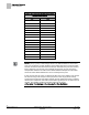
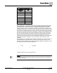
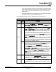
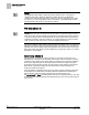
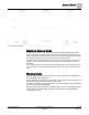
Table Of Contents
- Overview
- Sequence of Operation
- Average Face Velocity Control
- AVS Calibration
- AO2 Flow Signal
- Control Loop - Damper Application
- Venturi Application
- Minimum Exhaust Mode
- Maximum Exhaust Mode
- Warning Limits
- Alarm Limits
- Alarm Output
- Horn Disable
- Sash Area Alarms
- Table Access Feature
- Emergency Mode
- Start-up/Decommission Mode
- Fail Mode
- Wiring Diagrams
- Point Database Application 2941
- Point Database Application 2942
- Point Database Application 2900

Sequence of Operation
Alarm Limits
20
Siemens Industry, Inc. Application Note, Apps 2941/2942 140-1319
Restricted 2015-11-04
Warning and Alarm Schedule.
Alarm Limits
The Fume Hood Controller contains high and low flow alarm limits, HI ALM LMT and
LOW ALM LMT, respectively.
The alarm limits are defined as a percentage of the controller setpoint; therefore, the
alarm limits apply to EXH STPT during normal control.
For either of the alarms to become active, the alarm condition must be maintained for
the time specified in ALARM TIME.
When the actual flow is greater than HI ALM LMT or less than LOW ALM LMT for a
time greater than ALARM TIME, the red LED illuminates, HIGH ALM or LOW ALM
turns ON, the audible alarm on the Operator Display Panel sounds, “High Alarm” or
“Low Alarm” is displayed. See Figure
Warning and Alarm Schedule
.
Alarm Output
The digital output DO7 can be used for local indication of an alarm condition. The
output will be turned ON if EMER ALM, GEN FAILURE, LOW ALM, or HI ALM are ON
and the output will be OFF when they are all OFF.
Horn Disable
When the alarm silence button is pressed, ALM AKNLG turns ON, the audible alarm
turns OFF, and the red LED stays ON. The alarm descriptor remains until the flow
returns to the normal range and ALM AKNLG turns OFF. Alarm limits always override
any current warning limits.