
Application
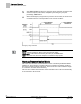
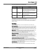
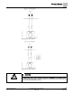
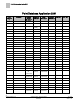
Table Of Contents
- Overview
- Sequence of Operation
- Average Face Velocity Control
- AVS Calibration
- AO2 Flow Signal
- Control Loop - Damper Application
- Venturi Application
- Minimum Exhaust Mode
- Maximum Exhaust Mode
- Warning Limits
- Alarm Limits
- Alarm Output
- Horn Disable
- Sash Area Alarms
- Table Access Feature
- Emergency Mode
- Start-up/Decommission Mode
- Fail Mode
- Wiring Diagrams
- Point Database Application 2941
- Point Database Application 2942
- Point Database Application 2900

Sequence of Operation
Start-up/Decommission Mode
22
Siemens Industry, Inc. Application Note, Apps 2941/2942 140-1319
Restricted 2015-11-04
3.
After EMER TIMER has timed out, the Fume Hood Controller controls the flow
at the flow setpoint, EXH STPT, multiplied by the emergency set point
percentage, EMER STPT.
4.
When the Emergency Purge button is pressed a second time, the Fume Hood
Controller returns to normal operation for the current conditions.
Emergency Purge Schedule.
NOTE:
Norm
= Normal operation in which control is at the EXH STPT.
EMER STPT
= EXH STPT increased by the value (%) of EMER STPT.
MAX
= Maximum flow, where the damper is controlled to fully opened.
Start-up/Decommission Mode
The Fume Hood Controller contains different modes controlled by STARTUP MODE
(default is 3). These modes of operation allow the controller to be started up without
the sound of nuisance alarms at the hood. These modes are useful at different stages
of construction and after decommissioning.
The FHC also contains decommission modes and allow some or all of the functionality
of the controller to be turned off.