
Application
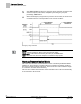
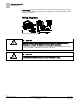
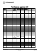
Table Of Contents
- Overview
- Sequence of Operation
- Average Face Velocity Control
- AVS Calibration
- AO2 Flow Signal
- Control Loop - Damper Application
- Venturi Application
- Minimum Exhaust Mode
- Maximum Exhaust Mode
- Warning Limits
- Alarm Limits
- Alarm Output
- Horn Disable
- Sash Area Alarms
- Table Access Feature
- Emergency Mode
- Start-up/Decommission Mode
- Fail Mode
- Wiring Diagrams
- Point Database Application 2941
- Point Database Application 2942
- Point Database Application 2900

Sequence of Operation
Fail Mode
23
Siemens Industry, Inc. Application Note, Apps 2941/2942 140-1319
Restricted 2015-11-04
The modes are described as an enumerated point:
STARTUP MODE
Mode
Description
0 Normal The controller is fully functional.
1 Decommission The controller is fully functional, except the flow
setpoint is set to 0, alarming is limited and the ODP
displays “Out of service” and “OFF”. If the sash is
opened, control is returned and you are notified that
the hood is “Out of service”.
2 Non-functional
Decommission,
closed
The controller is fully functional, except the flow
setpoint is set to 0, alarming is limited and the ODP
displays “Out of service” and “OFF”. If the sash is
opened, nothing changes.
3
(default)
Non-functional
Startup
The controller is fully functional, except alarming does
not work and the ODP displays “Controller – Startup”
and “OFF”.
To enter modes 1 and 2, the fume hood sashes must be in the closed position, and
FACE AREA must be smaller than UN ALRT AREA.
The digital output DO6 can be used for local indication that the sash was opened after
the hood entered Out of Service mode. The output will remain ON until STARTUP
MODE is changed.
Fail Mode
If the Fume Hood Controller or one of its accessories fails, then a failure mode
sequence is initiated.
Fume Hood Controller – If the Fume Hood Controller power fails, the exhaust damper
goes to the fully opened position. Since there is no power to the controller, no LEDs or
displays are available on the ODP. If the power fails to both the exhaust fan and the
controller, there is no indication except for the absence of the noise that the air makes
during normal operation.
Sash Sensor – If the sash sensor fails, then GEN FAILURE turns ON, and the Fume
Hood Controller maintains flow through the fume hood at an exhaust setpoint
calculated using the value in FAIL AREA and making FACE AREA equal to FAIL
AREA. The ODP displays FFF and GENERAL FAILURE.
Operator Display Panel – If the ODP fails, then the Fume Hood Controller continues to
control the flow. However, displays and audible alarms are not available.
OAVS Sensor – If the OAVS sensor fails or is disconnected, then GEN FAILURE turns
ON, AO2 goes to zero Vdc, and the Fume Hood Controller controls the exhaust
damper to the condition described in AVS FAILMODE. This will be either fully open or
holding the current position. The ODP displays the failure.
(Optional) Differential Pressure Transmitter – If A I3 is used and the differential
pressure transmitter fails by losing the 4 to 20 mA signal, then GEN FAILURE turns
ON, AO2 goes to 0 Vdc, and the Fume Hood Controller controls the exhaust damper to
the condition described in AVS FAILMODE. This will be either fully open or holding the
current position. The ODP displays the failure.
Electronic Actuator – If the actuator fails and flow control is lost, the ODP displays
alarms indicating unsafe operating conditions.
Upon loss of power the actuator will fail based on the related DIP switch settings.