
Application
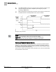
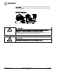
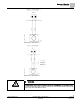
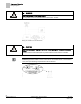
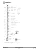
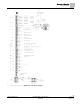
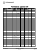
Table Of Contents
- Overview
- Sequence of Operation
- Average Face Velocity Control
- AVS Calibration
- AO2 Flow Signal
- Control Loop - Damper Application
- Venturi Application
- Minimum Exhaust Mode
- Maximum Exhaust Mode
- Warning Limits
- Alarm Limits
- Alarm Output
- Horn Disable
- Sash Area Alarms
- Table Access Feature
- Emergency Mode
- Start-up/Decommission Mode
- Fail Mode
- Wiring Diagrams
- Point Database Application 2941
- Point Database Application 2942
- Point Database Application 2900

Sequence of Operation
Wiring Diagrams
24
Siemens Industry, Inc. Application Note, Apps 2941/2942 140-1319
Restricted 2015-11-04
Face Velocity – If the Face Velocity falls out of the safe range of operation, the LOW
ALM or HIGH ALM turns ON and alarms are displayed on the ODP indicating unsafe
operating conditions.
Wiring Diagrams
Offboard Air Module Wiring.
CAUTION
The FHC-OAVS has two terminal blocks with terminations numbered identically
(terminations 1 through 16). DO NOT mix these up with each other.
If the FHC-OAVS is not connected as shown, it is not resistant to electrical surges. It
is also susceptible to interference from other equipment.
CAUTION
A separate power supply is required if a 4-20 mA sensor is used.
Failure to follow wiring precautions will result in equipment damage.