
Application
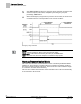
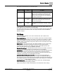
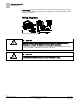
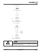
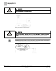
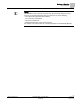
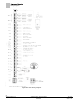
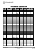
Table Of Contents
- Overview
- Sequence of Operation
- Average Face Velocity Control
- AVS Calibration
- AO2 Flow Signal
- Control Loop - Damper Application
- Venturi Application
- Minimum Exhaust Mode
- Maximum Exhaust Mode
- Warning Limits
- Alarm Limits
- Alarm Output
- Horn Disable
- Sash Area Alarms
- Table Access Feature
- Emergency Mode
- Start-up/Decommission Mode
- Fail Mode
- Wiring Diagrams
- Point Database Application 2941
- Point Database Application 2942
- Point Database Application 2900

Sequence of Operation
Wiring Diagrams
26
Siemens Industry, Inc. Application Note, Apps 2941/2942 140-1319
Restricted 2015-11-04
WARNING
Must use external 10 Vdc power supply.
Do not power AI from an onboard AO that is forced to 10 volts.
Wiring for AI with a 4 to 20 mA Sensor.
CAUTION
Each 4-20 mA sensor requires a SEPARATE dedicated power limited 24 Vdc power
supply.
DO NOT use the same transformer to power both the sensor and the controller.
NOTE:
If the voltage/current switch is set to current and a 4 to 20 mA sensor is connected to
an AI, then special wiring requirements must be followed.