
Application
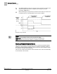
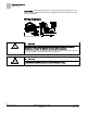
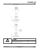
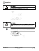
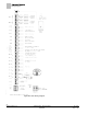
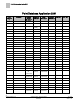
Table Of Contents
- Overview
- Sequence of Operation
- Average Face Velocity Control
- AVS Calibration
- AO2 Flow Signal
- Control Loop - Damper Application
- Venturi Application
- Minimum Exhaust Mode
- Maximum Exhaust Mode
- Warning Limits
- Alarm Limits
- Alarm Output
- Horn Disable
- Sash Area Alarms
- Table Access Feature
- Emergency Mode
- Start-up/Decommission Mode
- Fail Mode
- Wiring Diagrams
- Point Database Application 2941
- Point Database Application 2942
- Point Database Application 2900

Sequence of Operation
Wiring Diagrams
27
Siemens Industry, Inc. Application Note, Apps 2941/2942 140-1319
Restricted 2015-11-04
NOTE:
The controller’s DOs control 24 Vac loads only. The maximum rating is 12 VA for
each DO. An external interposing relay is required for any of the following:
• VA requirements higher than the maximum
• 110 or 220 Vac requirements
• DC power requirements
• Separate transformers used to power the load
(for example, part number 540-147, Terminal Equipment Controller Relay Module)