
Basic Documentation
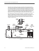
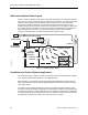
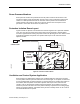

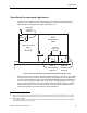
Table Of Contents

Laboratories
• It presents a greater design challenge and involves a more difficult startup and
balancing process. In particular, the areas adjacent to the room (for example,
corridors) must have the proper level of excess supply air since the laboratory
room(s) airflow tracking offset will not remain at a constant value.
Dual Pressurization Laboratories
In some instances, it is necessary to ensure that a laboratory room does not become
contaminated by airborne impurities from adjacent areas. Examples include laboratories with
microelectronics that must maintain a clean environment, or biological or pharmaceutical
laboratories that might be adversely affected by the inward airflow resulting from negative
room pressurization. When the substances present in a laboratory room do not present a
hazard to adjacent areas, positive room pressurization can be used to maintain an
uncontaminated room environment by the control methods described previously. However,
airflow tracking is generally the preferred method.
However, a more complex situation arises when laboratory rooms also use chemicals or
contain substances that are hazardous. In such circumstances, the adjacent areas (corridors
and non-laboratory areas of the building) must be protected by a design that ensures against
improper directional airflow for the laboratory room itself as well as the adjacent non-
laboratory areas.
Figure 6 shows how this can be achieved by using a dual pressurization arrangement for a
laboratory room. The same physical arrangement can be applied to virtually any type of
laboratory room regardless of its purpose or what it contains.
The major difference between Figure 6, and Figure 4 and Figure 5, is the addition of a
vestibule entryway for the laboratory. The laboratory room controller maintains the laboratory
at a positive static pressure by controlling the laboratory room supply airflow to always
exceed the laboratory’s total room exhaust by a fixed offset value. As a result, the laboratory
room is at a positive static pressure that prevents contaminants from entering the room.
However, the vestibule exhaust, in conjunction with the laboratory room's total exhaust,
exceeds the laboratory's supply airflow. As a result, the combined unit that consists of the
laboratory room and vestibule will be at a negative static pressure with respect to the
adjacent area.
The graph in Figure 6 illustrates that the combined exhaust airflow that consists of the
vestibule exhaust, plus the total room exhaust, exceeds the room supply airflow. The
resulting transfer airflows will be in the proper direction to prevent contamination of the
laboratory and also prevent any chemical fumes or other airborne agents from migrating out
from the laboratory into the adjacent area.
For example, the laboratory might have 300 cfm more supply airflow than its total exhaust.
The vestibule exhaust might be 500 cfm. This results in a net excess exhaust of 200 cfm for
the combination of laboratory and vestibule, and is therefore negative with respect to the
adjacent area. This arrangement keeps air from the adjacent areas from entering the
laboratory room and also prevents laboratory air from migrating into the adjacent area.
Siemens Building Technologies, Inc. 25