
Basic Documentation
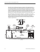

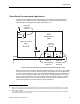
Table Of Contents

Room Pressurization Control Application Guide
Infectious Isolation Room Layout
Figure 7 shows the optimum room airflow and control arrangement for an infectious isolation
room. The room layout consists of the patient room and an anteroom. The anteroom provides
added assurance against airflow coming out from the patient room. The airflow control
arrangement maintains the patient room as the more negative of the two rooms so that
airflow is always into the anteroom and then into the patient room. The supply air diffuser and
the exhaust air grill in the patient room are located so that the airflow pattern is towards the
patient and then out of the room. This provides maximum protection for the building
occupants and in particular for workers who must enter the patient room.
SUPPLY
ROOM
CONTROLLER
ANTEROOM
EXHAUST
PATIENT ROOM
ROOM
PRESSURE
MONITORS
CAV EXHAUST
CONTROLLER
CFM
CFM
CFM
TRANSFER
AIRFLOW
DOOR DOOR
LAB0198R1
Figure 7. Infectious Isolation Room.
Ventilation and Control System Application
The ventilation system in Figure 7 provides an exhaust for both the anteroom and the patient
room, while the patient room alone has an air supply provision.
When operating, the anteroom exhaust might typically be approximately 50 cfm (24 L/sec),
while the patient room exhaust might be approximately 200 cfm (96 L/sec) greater than the
room supply airflow.
The patient room controller maintains the proper room supply and exhaust airflows, which
ensures that the proper airflow tracking offset is maintained. The patient room controller also
maintains the proper room ambient temperature. The anteroom exhaust is also maintained at
the proper airflow either by a separate CAV exhaust controller or the anteroom exhaust may
be maintained by another control function of the patient room controller.
28 Siemens Building Technologies, Inc.