
Basic Documentation
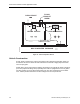
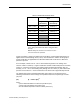
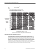

Table Of Contents

Clean Rooms
Table 3. Airlock Door Clearance Areas.
Total Closed Door Clearance
Area
Door Size
Hinged Door
(See Note 1)
Sliding Door
(See Note 2)
36 in. × 78 in. 0.229 sq. ft. 0.792 sq. ft.
36 in. × 84 in. 0.240 sq. ft. 0.833 sq. ft.
42 in. × 78 in. 0.245 sq. ft. 0.833 sq. ft.
42 in. × 84 in. 0.255 sq. ft. 0.875 sq. ft.
48 in. × 78 in. 0.875 sq. ft.
48 in. × 84 in. 0.917 sq. ft.
60 in. × 78 in. 0.958 sq. ft.
72 in. × 78 in. 1.042 sq. ft.
Note 1: Hinged door clearance area is based on
1/4 in. along the bottom and 1/8 in. along the sides
and top.
Note 2: Sliding door clearance area is based on 1/2 in.
around the entire door perimeter.
Figure 14 provides a graph of the airflow that results when a specific differential pressure is
applied across various leakage areas (curves). The information in Table 3 and the graph in
Figure 14 will help you approximate the differential airflow that results when a differential
pressure is present.
As an example, consider a 42 in. × 84 in. closed airlock hinged door. The leakage area
shown in Table 3 is 0.255 sq. ft. Figure 15 indicates that with a differential pressure of 0.0500
inches w.c. across the closed door, the resulting airflow would be approximately 150 cfm.
Similarly, a 72 in. × 78 in. closed sliding door (leakage area of 1.042 sq. ft.) with a differential
pressure of 0.02 inches w.c. across would result in an airflow rate of approximately 520 cfm.
The Differential Pressure and Differential Airflow data of Figure 14 is expressed by the
following pressurization versus leakage area equations based on inch-pound (IP) or metric
(SI) units:
(IP) Q = 2610 A (dP)
1/2
where:
Q is the differential airflow in Cubic Feet per Minute (cfm)
A is the total room leakage area Square Feet
dP is the differential pressure Inches of Water (inches w.c.)
Siemens Building Technologies, Inc. 39