
Basic Documentation
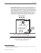
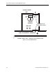
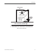
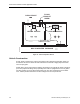
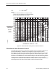
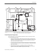

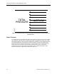
Table Of Contents

Room Pressurization Control Application Guide
(SI) Q = 840 A (dP)
1/2
where:
Q is the differential airflow in Liters per Second,
A is the total room leakage area in Square Meters
dP is the differential pressure in Pascals
DIFFERENTIAL
PRESSURE
INCHES
of
WATER
DIFFERENTIAL AIRFLOW - CFM
0.0500
0.0475
0.0450
0.0425
0.0400
0.0375
0.0350
0.0325
0.0300
00275
0.0250
0.0225
0.0200
0.0175
0.0150
0.0125
0.0100
0.0075
0.0050
0.0025
0.0000
0 50 100 150 200 250 300 350 400 450 500 550 600 650 700 750 800 850 900 950 1000
0.1 Ft
2
0.2 Ft
2
0.3 Ft
2
0.4 Ft
2
0.5 Ft
2
0.6 Ft
2
0.7 Ft
2
0.8 Ft
2
0.9 Ft
2
1.0 Ft
2
0.0600
0.0575
0.0550
0.0525
1.1 Ft
2
1.2 Ft
2
1.3 Ft
2
1.4 Ft
2
1.5 Ft
2
1.6 Ft
2
1.7 Ft
2
1.8 Ft
2
1.9 Ft
2
2.0 Ft
2
LEAKAGE AREA
CURVES
LAB0205R1
Figure 14. Airflows for Door Leakage Area vs. Differential Pressure.
Clean Room Static Pressure Control
Controlling the static pressure in clean rooms typically involves controlling individual static
pressure relationships in a multiple room arrangement. Figure 15 depicts such an
arrangement that consists of three separate clean rooms with an airlock entry. Each room
has a different positive static pressure level requirement, with the cleanest space at 0.20
inches w.c. The subsequent rooms are at 0.150 inches w.c. and 0.100 inches w.c. Finally,
the airlock is at 0.050 inches w.c. The corridor for entry into this clean room arrangement is
intended to be at a neutral (neither negative or positive) pressure. A series of Airflow
Leakage Arrows indicates the relative direction of airflow, which is always from the cleanest
area through each room space and then finally out to the Personnel Corridor.
40 Siemens Building Technologies, Inc.