
Basic Documentation
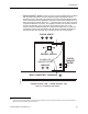
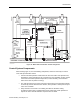

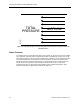
Table Of Contents

Clean Rooms
+0.100 in. w.c.
+0.150 in. w.c.
AIRFLOW
LEAKAGE
ARROWS
PERSONNEL CORRIDOR (NEUTRAL)
AIRLOCK
+0.050
in. w.c.
ROOM
CONTROLLER
ROOM STATIC
PRESSURE SENSOR
'CLEANEST'
SPACE
+0.200 in. w.c.
DS
DS
DS
DS
STATIC
PRESSURE
INPUTS
DOOR
SWITCH
INPUTS
MAKEUP
AIRFLOW
MAKEUP
AIRFLOW
MAKEUP
AIRFLOW
SUPPLY
ROOM
EXHAUST
ROOM
EXHAUST
EXHAUST
ROOM
EXHAUST
AIRFLOW MEASUREMENT
& CONTROL
INPUTS / OUTPUTS
DOOR SWITCH
LAB0206R1
Figure 15. Multi-room Pressurization Control Arrangement.
Control System Components
When viewing Figure 15, note the following components, which are necessary for overall
room static pressurization control:
• A Room Controller provides overall control for all of the rooms' static pressure and,
although the control components are not shown, the room controller can also control
each room environment (ambient temperature, relative humidity, and sometimes
other factors such as particle counting).
• The static pressure level of each room space with respect to the Personnel Corridor
is sensed by a Room Static Pressure Sensor, which provides a static pressure input
to the room controller
• Entry and exit to each room is via a sliding door with an automatic closing
arrangement. Each door is equipped with a Door Switch (DS), which provides an
input to the room controller when the respective door is closed.
Siemens Building Technologies, Inc. 41