Fume Hood Sash Open Area Module (SOAM) Application 2956: 2 Vertical sashes, with Top Sash having 2 to 8 Horizontal Sashes – Floor Mounted Configuration Start-up Procedures Building Technologies A6V10801617 07.06.
Table of Contents Before You Begin ..................................................................................................3 Verifying Power .........................................................................................................3 Installing USB Driver .................................................................................................3 Verifying Slave Mode Application ..............................................................................
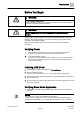
Before You Begin Verifying Power Before You Begin WARNING A fume hood is a safety device. Anyone attempting to start up a Fume Hood Controller and its related equipment must have completed Operations Training. WARNING DO NOT connect to the USB port of the SOAM while the fume hood is in operation. At the job site, locate the major control system and the mechanical and electrical drawings. This should include any components working in conjunction with the Sash Open Area Module (SOAM).
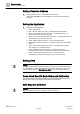
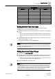
Before You Begin Setting Controller Address Setting Controller Address 1. If using the sensor bus to communicate the face area: Verify CTLR ADDRESS is correct (default is 51 and does not need to be changed). Setting the Application 1. Select the desired application.
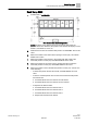
Before You Begin Fume Hood Specific Sash Setup and Calibration Sash Setup 2956 1. Set REPORT to OVERVIEW. Nine Combination Sash Configuration. NOTE: Numbers on the sashes show how the sash is wired. After the physical sashes are calibrated, the position of the sashes will display in POS SASH 1, POS SASH 2, and so on. 2. Determine the number of horizontal sash panels. Set HZ PANEL CNT to this value. 3. Measure the width of the vertical sash opening in inches (cm). Set VSASH WIDTH to this value. 4.
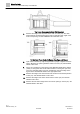
Before You Begin Fume Hood Specific Sash Setup and Calibration Top Frame Measurement with Air Foil Removed. 7. Measure the height of the top frame of the sash in inches (cm). The sash frame holds the horizontal sash panels and occupies the outer edges of the fume hood opening. Set TOP FRAME to this measured value. Vertical Sash Fume Hood with Bypass Area Open and Closed. 8. Open sash 1 until the top edge is aligned with top edge of bypass and close sash 2.
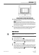
Before You Begin Fume Hood Specific Sash Setup and Calibration Example Combination Sash Fume Hood with Fixed Area. 13. Measure the fixed area of the fume hood in square feet (square meters). Any fume hood leakage must be accounted for in this measurement. Set FIXED AREA to this value. NOTE: The fixed area of the fume hood is an area that remains open regardless of sash position or movement.
Before You Begin Fume Hood Specific Sash Setup and Calibration 7. Repeat Steps 2 through 6 for the second vertical sash. 8. Set CAL SASH NUM back to 0 or to the first horizontal sash, number 3, to be calibrated. This locks to sash calibration into the sash aggregator. 9. Set CAL SASH LOC to MIN for minimum opening. 10. Slide the sash panel to be calibrated to the far left. Measure the distance from the left end of the track to the left edge of the sash panel. Set CAL SASH POS to this value.
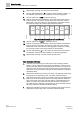
Before You Begin Setting External Face Area Input Sash Point/Wiring. Sash Panel Point Descriptor Vertical 1 31 POS SASH 1 Vertical 2 32 POS SASH 2 Horizontal 3 33 POS SASH 3 Horizontal 4 34 POS SASH 4 Horizontal 5 35 POS SASH 5 Horizontal 6 36 POS SASH 6 Horizontal 7 37 POS SASH 7 Horizontal 8 38 POS SASH 8 Horizontal 9 39 POS SASH 9 Horizontal 10 40 POS SASH 10 Setting External Face Area Input Skip this section if you are only using one SOAM, leave values at default.
Before You Begin Flashing Controller Firmware AO DEADBAND defaults to 0%. If FACE A OUT changes by less than the percentage value in AO DEADBAND, the output will not update. Once the value changes greater than the AO DEADBAND, the output will be updated to the currently calculated value. If needed, set MIN FA VOLTS (default = 1 Vdc). MIN FA VOLTS can be left at default for most installations. Changing this value changes the voltage output when the FACE AREA = 0 sq ft.
Issued by Siemens Industry, Inc. Building Technologies Division 1000 Deerfield Pkwy Buffalo Grove IL 60089 +1 847-215-1000 © Siemens Industry, Inc., 2016 Technical specifications and availability subject to change without notice. Document ID: A6V10801617 Edition: 07.06.