
Commissioning Instructions

Before You Begin
Setting External Face Area Input
9 | 11
Siemens Industry, Inc.
A6V10801617
Restricted
07.06.2016
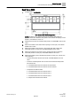
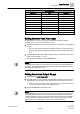
Sash Point/Wiring.
Sash Panel
Point
Descriptor
Vertical 1
31
POS SASH 1
Vertical 2
32
POS SASH 2
Horizontal 3
33
POS SASH 3
Horizontal 4
34
POS SASH 4
Horizontal 5
35
POS SASH 5
Horizontal 6
36
POS SASH 6
Horizontal 7
37
POS SASH 7
Horizontal 8
38
POS SASH 8
Horizontal 9
39
POS SASH 9
Horizontal 10
40
POS SASH 10
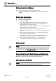
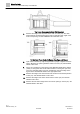
Setting External Face Area Input
Skip this section if you are only using one SOAM, leave values at default.
AI can be set up as an input for external face area.
1. Set MAX EXT AREA to the area corresponding to 10 volts from the input signal
source.
The next step allows the minimum voltage to bet set to a value other than 1
(default). The minimum voltage is represented when the face area is equal
to 0.
2. Set MIN EXTVOLTS to the voltage corresponding to 0 face area from the input
signal source. (default = 1.0 Vdc)
The resulting area displays in point EXTERNAL A.
NOTE:
If no external area input is be connected to the AI, make sure MAX EXT AREA =
0 (default). This disables the alarm feature that fails the FACE AREA point when
the input signal drops below 1 Vdc.
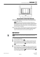
Setting Face Area Output Range
1. Set REPORT to FACE AREA OUT.
2. Set MAX FACE A to the maximum expected face area for the fume hood, plus
approximately 10%. Example: If the maximum face area is 9 sq ft, set it to 10.
FACE A OUT is now active and a proportional 1 to 10V signal can be read
on AO. 1V equals 0 sq ft and 10V = MAX FACE A.
3. Set AO DEADBAND to the desired value.
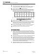
NOTE:
AO DEADBAND can be set from 0 to 100% in 0.4% increments. 0% will give the
actual face area all the time. If a sash input signal is unstable, this will cause an
unstable reading to be sent to the output which could cause short-term instability
or control problems. Increase the values to give a stable output and remove the
signal bounce. A 10% deadband is equal to a ± 5% of the face area.