
Installation Instructions

Installation Instructions
Document No. 550-165
October 26, 2016
LCM-OAVS Room Pressurization Slow
Actuation
Item No. 550-165. Rev. BA Page 1 of 11
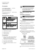
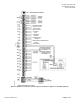
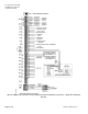
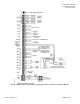
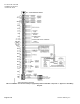
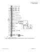
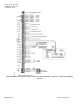
Generic Controller I/O Layout. See Wiring Diagram for application specific details.
Control Applications
2922, 2923, 2924, 2928, 2929, 2930
Product Description
These instructions explain how to field install or
replace the Laboratory Controller Module LCM.
This LCM-OAVS VAV Room Pressurization with HW
Reheat and Damper Actuation — One Exhaust, One
Supply features VAV control of a laboratory room
with one supply duct, one exhaust duct, and up to
six Fume Hoods. It uses fast-acting electronic
actuators (shipped separately) to control the supply
and exhaust.
The LCM can operate stand-alone, with a field
panel, or as part of a network.
Product Numbers
LCM-OAVS Slow Actuation Venturi
Supply/Venturi Exhaust Applications
2922 (RTS) 2928 (BTU)
550-767DN
LCM-OAVS Slow Actuation Damper
Supply/Damper Exhaust Applications
2923 (RTS) 2929 (BTU)
550-767FN
LCM-OAVS Slow Actuation Damper
Supply/Venturi Exhaust Applications
2924 (RTS) 2930 (BTU)
550-767GN
Offboard Air Module – two required,
order separately
550-819B
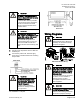
Shipping carton includes a controller assembly, a
mounting rail, and two self-tapping/drilling screws.
CAUTION
Keep the unit in its static-proof bag
until installation.
Otherwise, you run the risk of
damage to the printed circuit board
from electrostatic discharge.