
Installation Instructions

Document No. 550-165
Installation Instructions
October 26, 2016
Siemens Industry, Inc. Page 3 of 11
CAUTION
DO Wiring – Each DO provides a
Normally Open (NO) terminal and a
Common (C) terminal.
To reduce noise and the potential
for ground loops, both connections
of a 24 Vac load must be wired
directly to the DO terminal on the
controller board.
CAUTION
The fume hood flow module, the
FHC, any 0 to 10 Vdc actuator used
by the LCM, and the LCM cannot
share a single power trunk.
The preferred configuration for
shared power trunks is to use one
trunk for the FFM and FHC and
another trunk for the actuator(s) and
LCM.
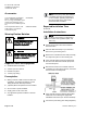
8.
Plug the room temperature sensor cable into
the RTS port.
9.
Connect the power trunk. DO NOT apply
power to the controller without first consulting
the specialist.
CAUTION
It is important that the neutral
that supplies the TEC must be
earth grounded at the source
of the 24 Vac power.
Possible erratic equipment
operation or damage if neutral
is not grounded.
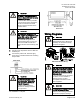
The installation is complete.
Dimensions.
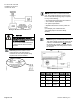
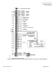
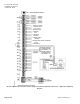
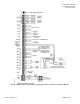
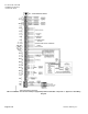
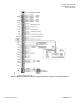
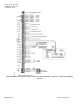
Wiring Diagrams
CAUTION
Controllers will be
damaged/destroyed if offboard air
module(s) are not wired correctly
and power is applied.
Offboard Air Module Wiring.
CAUTION
The LCM-OAVS has two terminal
blocks with terminations numbered
identically (terminations 1 through
16). DO NOT get these mixed up
with each other.
If the LCM-OAVS is not connected
as shown, it is not resistant to
electrical surges. It is also
susceptible to interference from
other equipment.
CAUTION
A separate power supply is required
if a 4-20 mA sensor is used.
Failure to follow wiring precautions
will result in equipment damage.