PRC-OAVS Pressurization Control by Differential Flow Reset, with Heating by BTU Compensation Slow Actuation, Floating or Analog Output Owner’s Manual 125-5111 125-5111 2015-06-30 Building Technologies
Table of Contents How To Use This Manual .................................................................................................. 4 Chapter 1 – Product Overview ......................................................................................... 6 Hardware Inputs .................................................................................................................. 7 Hardware Outputs ...................................................................................................
How To Use This Manual How To Use This Manual This manual is written for the owner and user of the PRC-OAVS with Pressurization Control by Differential Flow Reset, Slow Actuation, Floating or Analog Output and Heating by BTU Compensation. It is designed to help you become familiar with the Siemens Pressurization Room Controller and its applications. This section covers manual organization, manual conventions, symbols used in the manual, and other information that will help you use this manual.
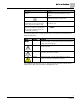
How To Use This Manual Convention Examples New terms appearing for the first time are The field panel continuously executes a useritalicized. defined set of instructions called the control program. This symbol signifies Notes. Notes provide additional information or helpful hints. Cross references to other information are For more information on creating flowcharts, see indicated with an arrow and the page Flowcharts [→92].
Chapter 1 – Product Overview Hardware Inputs Chapter 1 – Product Overview The PRC-OAVS with Pressurization Control by Differential Flow Reset, Slow Actuation, Floating or Analog Output and Heating by BTU Compensation is the Siemens Industry FLN controller used in pressure independent Variable Air Volume applications. It provides Direct Digital Control (DDC) for a number of applications.
Chapter 1 – Product Overview Hardware Inputs Hardware Inputs Analog Air velocity sensor (one or two depending on setup) Application 2931 Room temperature sensor Application 2931 Discharge temperature sensor (10K (default) or 100K Ω software selectable thermistor) Application 2931 Differential pressure sensor (0-10 Vdc or 4-20 mA) Application 2931 Digital Occupancy button (option on room temperature sensor) Application 2931 (Optional) Occupancy switch Application 2931 (Optional) Alarm switch Ap
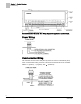
Chapter 1 – Product Overview Power Wiring Generic Controller I/O Layout. See Wiring Diagram for application specific details. Power Wiring Communication Wiring The controller connects to the field panel by means of a Floor Level Network (FLN) trunk. Communication wiring connects to the three screw terminals on the controller labeled “+” (positive), “-“ (negative), and “ ” (reference). 8 Siemens Industry, Inc.
Chapter 1 – Product Overview Temperature Sensors Temperature Sensors Temperature sensors used with the PRC-OAVS with Pressurization Control by Differential Flow Reset, Slow Actuation, Floating or Analog Output and Heating by BTU Compensation include an electronic room temperature sensor and an optional duct temperature sensor. Room Temperature Sensor The controller room temperature sensor connects to the controller by means of a cable terminated at both ends with a six-conductor RJ-11 plug-in connector.
Chapter 2 – Applications Basic Operation Chapter 2 – Applications Basic Operation The PRC-OAVS with Pressurization Control by Differential Flow Reset, Slow Actuation, Floating or Analog Output and Heating by BTU Compensation provides Direct Digital Control (DDC) technology for pressure independent Variable Air Volume (VAV) and Constant Volume (CV) laboratory room applications.
Chapter 3 – Point Database Chapter 3 – Point Database Chapter 3 presents a description of the PRC-OAVS with Pressurization Control by Differential Flow Reset, Slow Actuation, Floating or Analog Output and Heating by BTU Compensation point database, including point descriptors, point addresses, and a listing of applications in which each point is found. Address1 Application CTLR ADDRESS 01 All Identifies the controller on the FLN trunk.
Chapter 3 – Point Database Address1 Application Description OCC BUTTON {19}2 All Actual indication of the status of the override switch (not physically available on all temperature sensor models) at the room temperature sensor. ON indicates that the switch is being pressed. OFF indicates that the switch is released. Valid input: ON or OFF. OCC.UNOCC {21} All Indicates the mode that the controller is operating in with respect to the override switch.
Chapter 3 – Point Database Address1 Application OCC GEX MN {34} 2931 The minimum amount of exhaust in cfm (lps) to be supplied to the space during occupied periods SUP AIR VOL {35} 2931 Measured value of the supply airflow. AIR VOLUME 1 {35} 2997 Measured value of airflow in cfm (lps). SUP FLO COEF 36 2931 Calibration factor for airflow. FLOW COEFF 1 36 2997 Calibration factor for airflow. REHEAT AO1 {37} 2931 The control signal for the Reheat Valve (0-10V).
Chapter 3 – Point Database Address1 Application 52 2931 Sets the presence or absence of a motor and its direction of travel. TOTL EXHAUST {53} 2931 This value is the sum of the measured value of the airflow from the room through the general exhaust terminal, the airflow through the fume hoods, and any exhaust flows not connected to the PRC. GEX FLO COEF 54 2931 The calibration parameter for airflow sensor. FLOW COEFF 2 54 2997 Calibration parameter for airflow sensor.
Chapter 3 – Point Database Address1 Application Description 76 2931 Determines type of control, VAV or CV, during occupied and unoccupied modes. DO 6 {77} 2931 Digital output 6 controls a 24 Vac load with an ON or OFF status. If Motor 3 is enabled, then DO 5 is coupled with DO 6 to control an actuator. CTL TEMP {78} 2931, 2997 TEMP LOOPOUT {79} 2931 The value calculated by the room temperature PID algorithm. It indicates the thermal load on the room.
Chapter 3 – Point Database Address1 Application SUPDUCT AREA 97 2931, 2997 LOOP TIME 98 2931 The time, in seconds, between control loop calculations. ERROR STATUS {99} 2931, 2997 The status code indicating any errors detected during controller power up. A status of 0 indicates there are no problems. REHEAT CLOSD 102 2931 The value of REHEAT AO1 that closes the reheat valve completely. REHEAT OPEN 103 2931 The value of REHEAT AO1 that opens the reheat valve completely.
Chapter 3 – Point Database Address1 Application SUP DMP OPEN 121 2931 The value of SUP DMP AO2 that open the damper all the way. GEX DMP CLOS 122 2931 The value of GEX DMP AO3 that closes the damper all the way. GEX DMP OPEN 123 2931 The value of GEX DMP AO3 that open the damper all the way. NO PR VOL DF 125 2931 The value in CFM that the room is controlled to if the room pressure sensor fails.
Chapter 4 – Basic Service and Maintenance Basic Service Information Chapter 4 – Basic Service and Maintenance This chapter describes corrective measures you can take should you encounter a problem when using a Pressurization Room Controller. You are not required to do any controller troubleshooting. You may want to contact your local Siemens Industry representative if a problem occurs or you have any questions about the controller.
Glossary Glossary This glossary contains the collected terms and acronyms that are used in Siemens BACnet PTEC and TEC Controllers. For definitions of point database descriptors, see Chapter 3 - Point Database, in this manual. airflow Rate at which a volume of air moves through a duct. Usually expressed in cubic feet per minute (cfm) or liters per second (lps). algorithm Mathematical formula and control logic that uses varying inputs to calculate an output value. AVS Air Velocity Sensor.
Glossary Demand Control Ventilation A control algorithm that provides for the control or reduction of outdoor air intake below design rates when the actual occupancy of spaces served by the system is at less than design occupancy. DCV Demand Control Ventilation. DDC Direct Digital Control. Direct digital control The automated control of a condition or process by a digital device (computer). DO Digital Output. Physical output point that sends a two-state signal (ON/OFF, OPEN/CLOSED, YES/NO).
Glossary HMI Human Machine Interface. Terminal and its interface program that allows you to communicate with a field panel or equipment controller. Occupancy sensor A control device that detects presence of people in a space by using infrared or ultrasonic technology. Occupancy sensors are used to save energy by controlling lighting and temperature and, along with CO2 sensors, to provide control input of demand control ventilation (DCV) algorithms.
Glossary UI Universal Input. Can be used as an AI or DI. An AI input is a point receiving a signal that represents a condition that has more than two states. A DI input is a physical input point that receives a two-state signal. unbundle Term used to describe the entering of a point that resides in a controller's database into the field panel's database so that it can be monitored and controlled from the field panel. VAV Variable air volume.
Index Index A L actuators, 9 damper actuator, 9 valve actuator, 9 algorithm, 19 application, slave mode overview, 10 loopout, 20 B P basic operation, 10 basic service information, 18 PID, 21 point database overview, 11 preventive maintenance, 18 C centralized control, 19 Chilled Beam, 19 CO2, 19 control loop, 19 controller Terminal Box (VAV) Controller, 6 Terminal Equipment Controller, 6 CV, 19 D DCV, 20 DDC, 20 Demand Control Ventilation, 20 Direct digital control, 20 Direct Digital Control (DDC)
Issued by Siemens Industry, Inc. Building Technologies Division 1000 Deerfield Pkwy Buffalo Grove IL 60089 Tel. +1 847-215-1000 Document ID 125-5111 Edition 2015-06-30 © Siemens Industry, Inc., 2015 Technical specifications and availability subject to change without notice.