
Operating Instructions
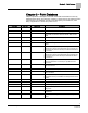

Chapter 3 – Point Database
12
Siemens Industry, Inc.
Owner's Manual
125-5111
2015-06-30
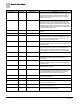
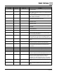
Descriptor
Address
1
Application
Description
OCC BUTTON
{19}
2
All
Actual indication of the status of the override switch (not
physically available on all temperature sensor models) at the
room temperature sensor. ON indicates that the switch is
being pressed. OFF indicates that the switch is released.
Valid input: ON or OFF.
OCC.UNOCC
{21}
All
Indicates the mode that the controller is operating in with
respect to the override switch. NIGHT indicates that the
switch has not been pressed and the override timer is not
active. DAY indicates that the switch has been pressed and
the override timer is active. The controller then uses a day
mode temperature setpoint. This point is only in effect when
DAY.NGT indicates night mode.
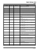
VOL DIF ALM
{22}
2931
Alarm point. ON means room pressurization may not be
adequate.
NET ALM CMD
{23}
2931, 2997
The alarm data sent in to PRC from the network.
OCC SWIT DI2
{24}
2931, 2997
Actual status of a contact connected to the controller at DI 2
(screw terminals 15 and 16). ON indicates that the contact is
closed; OFF indicates that the contact is open. If a wall
switch is used, it is connected to DI 2.
DI 2
{24}
2997
Actual status of a contact connected to the controller at DI 2.
ON indicates that the contact is closed; OFF indicates that
the contact is open.
BUTTON CMD
{25}
2
All
Actual status of a contact connected to the controller at DI
3/AI 3 (screw terminals 13 and 14). ON indicates that the
contact is closed; OFF indicates that the contact is open.
When a contact is connected at DI 3, AI 3 is not available.
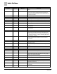
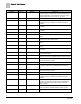
GEX P GAIN
26
2931
Feedback gain. Used to tune general exhaust flow control
loop.
ALM SWIT DI6
{27}
2931
Set the controller to Supply Tracks Exhaust (negative
pressurization) or Exhaust Tracks Supply (positive
pressurization).
DI 6
{27}
2997
Actual status of a contact connected to the controller at DI 6.
ON indicates that the contact is closed; OFF indicates that
the contact is open.
TRACK MODE
28
2931
An occupancy input. This value comes to the LCM from the
network or from a schedule.
NET OCC CMD
{29}
2931
Indicates the mode in which the controller is operating.
Occupied temperature setpoints will be used in DAY mode.
Unoccupied temperature setpoints will be used in NGT
mode. This point is normally set by the field panel.
GEX AIR VOL
{30}
2931, 2997
Measured value of the airflow from the room through the
general exhaust terminal.
AIR VOLUME 2
{30}
2997
Measured value of airflow in cfm (lps).
OCC SUP MAX
{31}
2931
The maximum amount of air in cfm (lps) to be supplied to the
space during occupied periods.
OCC SUP MIN
{32}
2931
The minimum amount of air in cfm (lps) to be supplied to the
space during occupied periods
OCC GEX MAX
{33}
2931
The maximum amount of exhaust in cfm (lps) to be supplied
to the space during occupied periods.