
Operating Instructions

Chapter 3 – Point Database
15
Siemens Industry, Inc.
Owner's Manual
125-5111
2015-06-30
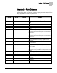
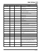
Descriptor
Address
1
Application
Description
VOLUME STATE
76
2931
Determines type of control, VAV or CV, during occupied and
unoccupied modes.
DO 6
{77}
2931
Digital output 6 controls a 24 Vac load with an ON or OFF
status. If Motor 3 is enabled, then DO 5 is coupled with DO 6
to control an actuator.
CTL TEMP
{78}
2931, 2997
The temperature used as input for the temperature control
loops. This value will be the same as the value in ROOM
TEMP, unless it is overridden.
TEMP LOOPOUT
{79}
2931
The value calculated by the room temperature PID algorithm.
It indicates the thermal load on the room.
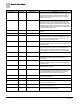
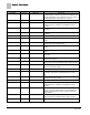
DISCH P GAIN
80
2931
Proportional feedback gain used to tune the discharge
temperature control.
DISCH I GAIN
81
2931
Integral feedback gain used to tune the discharge
temperature control.
DMPR STATUS
{82}
2931
Indicates whether or not the damper positions are being
recalculated.
VOL DIFF
{83}
2931
The difference between measured airflow into the room, and
measured airflow out.
DISCH TEMP
{84}
2931
Discharge temp sensor input.
GEX FLO STPT
{85}
2931
The desired value of the general exhaust. The controller
selects the lowest value that will lead to adequate supply
flow, and correct pressurization.
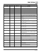
FAIL LIMIT
86
2931
The error threshold of the Supply or Exhaust (depending on
TRACK MODE) above which the FLOW MODE switches
from STPT to FLOW after the time in FAIL TIME has expired.
LO PRES RNG
87
2931
The lowest value that the sensor connected to RM PRES AI3
will read.
VOL DIF STPT
{88}
2931
The desired value for the flow difference. This value can be
selected and adjusted to achieve room pressurization
OTHER EXH
{89}
2931
The value of any exhaust airflows not connected to the LCM.
Must be entered to the controller to account for flows it
cannot detect.
OC V ALM LVL
90
2931
Low Ventilation alarm level (cfm/lps) for occupied mode.
UC V ALM LVL
91
2931
Low Ventilation alarm level (cfm/lps) for unoccupied mode.
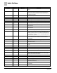
VENT ALM
{92}
2931
Alarm point indicates inadequate air change rate.
SUP FLO STPT
{93}
2931
The desired value of the supply flow, chosen by the
controller, to achieve the correct flow difference for the room.
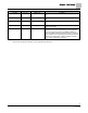
CAL AIR
{94}
2931, 2997
YES commands the controller to go through calibration
sequence for the air velocity transducers. YES is also
displayed when the calibration sequence is started
automatically. CAL AIR automatically returns to NO after the
calibration sequence is completed. Valid input: YES or NO
CAL SETUP
95
2931, 2997
The configuration setup code for the calibration sequence
options.
CAL TIMER
96
2931, 2997
Time interval, in hours, between the calibration sequence
initiations if a timed calibration option is selected in CAL
SETUP.