LCM-OAVS Room Pressurization with Fastacting Damper Actuation (One Exhaust, One Supply), Hot Water Reheat and BTU Compensation, Application 2927 Application Note 140-1311 2015-07-07 Building Technologies
Table of Contents Overview ............................................................................................................................. 5 Hardware Inputs .................................................................................................................. 6 Hardware Outputs ................................................................................................................ 7 Ordering Notes .............................................................................
Fail Mode Operation .......................................................................................................... 26 Application Notes ............................................................................................................... 28 Wiring Diagram .................................................................................................................. 29 Point Database Application 2927 ...................................................................................
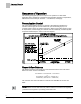
Overview Hardware Inputs Overview Application 2927 controls pressurization, ventilation, and room temperature in a laboratory room served by one single-duct supply terminal with a reheat coil, one general exhaust terminal, and up to six fume hoods (multiple fume hood flow signals must be averaged using an averaging and scaling module. Pressurization is controlled by maintaining a selected difference between supply and exhaust airflows.
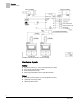
Overview Hardware Inputs Ventilation and Pressurization Control Drawing. Hardware Inputs Analog Air velocity sensor (s) – (one or two depending on setup) Fume hood controller input or FFM Room temperature sensor Discharge Temperature Sensor (10K Ω thermistor) Digital Occupancy button (option on room temperature sensor) (Optional) Occupancy switch (Optional) Alarm switch 6 Siemens Industry, Inc.
Overview Hardware Outputs Hardware Outputs Analog Reheat valve Digital Autozero Solenoid in Offboard Air Module (DO 8) (Optional) Alarm Supply damper (two DOs) General exhaust damper (two DOs) Ordering Notes 550-767EN LCM-OAVS Room Pressurization with Fast-acting Damper Actuation (One Supply, One Exhaust) and Hot Water Reheat Requires Offboard Air Module(s) – order and ship separately 550-819B Offboard Air Module (OAM) – order and ship separately GNP191.
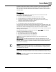
Sequence of Operation Pressurization Control Sequence of Operation The following paragraphs present the sequence of operation for LCM-OAVS Application 2627: Variable Air Volume Room Pressurization with BTU Compensation, HW Reheat and Fast Damper Actuation — One Exhaust, One Supply. Pressurization Control The goal of pressurization control is to maintain a fixed difference between the volumes of total supply air and total exhaust air (see the following figure).
Sequence of Operation Occupancy Application 2927 has the ability to maintain a different volume differential setpoint during occupied mode than during unoccupied mode. When OCC.UNOCC = OCC, VOL DIF STPT = OCC DIF STPT. When OCC.UNOCC = UNOCC, VOL DIF STPT = UOC DIF STPT. Occupancy The controller keeps track of the occupancy status of the room and uses that information for the following purposes: To select minimum and maximum flow rates for each air terminal.
Sequence of Operation Active Flow Minimums and Maximums The following table shows what is enabled when OCC ENA is at a particular value. OCC ENA Values. OCC ENA (value) 0 (default) Description Both OCC BUTN DI1 and OCC SWIT DI2 are disabled. 1 Only OCC BUTN DI1 is enabled. 2 Only OCC SWIT DI2 is enabled. NOTE: OCC ENA does not allow both OCC BUTN DI1 and OCC SWIT DI2 to be enabled at the same time. If OCC ENA is set greater than 2, it will default to 0.
Sequence of Operation VAV versus CV Control VAV versus CV Control In Application 2927, VAV means that the supply airflow can be varied to provide cooling. CV means the supply airflow is not a source of cooling. However, the supply and general exhaust can still change in CV mode to keep the volume differential setpoint constant. This may be necessary if HOOD VOL is varying. Application 2927 can do either Variable Air Volume control (VAV) or Constant Air Volume Control (CV).
Sequence of Operation Flow Tracking – Supply Tracks Exhaust vs. Exhaust Tracks Supply NOTE: If desired, the LCM can be used without any fume hoods attached. In this case, MAX HOOD VOL should be set to 0 cfm to disable the alarming that would occur if the fume hood flow input drops below 1 Vdc. Flow Tracking – Supply Tracks Exhaust vs.
Sequence of Operation Calculating Exhaust Flow Setpoint TRACK METHOD TRACK METHOD is a point associated with TRACK MODE. TRACK MODE determines which airflow (supply or general exhaust) gets tracked and which airflow does the tracking. TRACK METHOD determines how tracking is accomplished. If TRACK MODE is set to ETS and TRACK METHOD is set for FLOW tracking, the general exhaust flow setpoint is calculated according to the measured value, SUP AIR VOL.
Sequence of Operation Calculating Supply Flow Setpoint To calculate GEX FLO STPT, the controller determines the general exhaust airflow value that pressurizes the room based on the values of VOL DIF STPT, OTHER EXH, OTHER SUP and either SUP FLO STPT or SUP AIR VOL depending on the value of TRACK METHOD.
Sequence of Operation Ventilation – VAV Mode Ventilation – VAV Mode During VAV operation, the ventilation works as follows: OCC SUP MIN, the occupied supply minimum, is used to ensure that the room receives enough supply air for proper ventilation during the occupied mode. UOC SUP MIN is used to ensure that the room receives enough supply air for proper ventilation during the unoccupied mode.
Sequence of Operation Airflow Control When calibration is in progress, CAL AIR equals YES. After calibration, CAL AIR returns to NO. The application uses Autozero Modules connected to AUTOZERO DO8. This means that the supply and general exhaust flow control devices do not close during calibration of the transducers. NOTE: The LCM does not monitor Fume Hood flow changes for 3 seconds during AVS calibration.
Sequence of Operation Room Temperature and Setpoint Room Temperature and Setpoint The application uses the CTL STPT as the setpoint for the Room Temperature PID Loop. When CTL STPT is not overridden and not being controlled by a field panel, then ROOM STPT and CTL STPT are related to each other as follows: If ROOM STPT is greater than RM STPT MAX, then CTL STPT is set equal to RM STPT MAX. If ROOM STPT is less than RM STPT MIN, then CTL STPT is set equal to RM STPT MIN.
Sequence of Operation Room Unit Operation Room Unit Operation Sensor Select SENSOR SEL is a configurable, enumerated point (values are additive). This point tells the controller what type of room unit is being used and how to handle loss of communication, for more information see Fail Mode Operation [➙ 26]. It also provides the ability to enable the optional RH and CO2 sensors and indicates which thermistor type is connected.
Sequence of Operation Temperature Control Loops Room CO2 RM CO2 displays the CO2 value in units of parts-per-million (PPM). RM CO2 (from the digital 2200/2300 room units) can be used with PPCL in the PTEC/ATEC controller or unbundled for control or monitoring purposes. Room RH RM RH displays the relative humidity value in percent. RM RH can be used for PPCL in the PTEC or unbundled for control or monitoring purposes. RM RH displays the relative humidity value in percent.
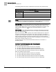
Sequence of Operation BTU Calculations The output of the room temperature loop, TEMP LOOPOUT, reflects the load requirements. The value of TEMP LOOPOUT is a supply air temperature expressed as “degrees above or below the room temperature setpoint if the supply flow is at 100%”. If the supply flow is less than 100% of the currently active air supply airflow maximum, DISCH STPT is adjusted to an amount greater than TEMP LOOPOUT by a corresponding percentage. Example CTL STPT = 70°F: OCC.
Sequence of Operation BTU Calculations Temperature Control Sequence. BTU Calculations – Constant Volume Mode During the Constant Volume Mode, the BTU Compensator operates as follows: During Constant Volume operation, the controller adjusts the supply air temperature set point as necessary to maintain CTL TEMP at CTL STPT. The room temperature PID loop calculates the value of TEMP LOOPOUT. This value is used to adjust the value of the supply air temperature set point.
Sequence of Operation Alarms CTL STPT = 70°F: OCC.UNOCC = UNOCC If TEMP LOOPOUT = and SUP AIR VOL = then DISCH STPT = Formula for DISCH STPT: CTL STPT + (TEMP LOOPOUT x 100% ÷ SUP AIR VOL) 10°F UOC SUP MAX 80°F 70° + (10° x 100% ÷ 100%) 10°F 0.5 ´ UOC SUP MAX 90°F 70° + (10° x 100% ÷ 50%) –5°F 0.
Sequence of Operation Alarms GEX AIR VOL stays below the currently active general exhaust box minimum, for a time at least equal to VENT ALM DEL. It is turned off only when all of the following conditions are true: The TOTL SUPPLY stays above the alarm level, for a time at least equal to the alarm delay. SUP AIR VOL stays above the currently active supply minimum, for a time at least equal to VENT ALM DEL.
Sequence of Operation Alarms Local Annunciation ALARM ENA is an analog point whose value determines whether or not a particular alarm activates ALARM DO7. For ALARM ENA, the terms enabled and not enabled do not mean that a particular alarm is enabled or not. It means whether or not a particular alarm will or will not activate ALARM DO7. For example, if ALARM ENA is set to 1 (Vent Alarm Enabled) and a ventilation alarm occurs, then both VENT ALM and ALARM DO7 will turn on.
Sequence of Operation Damper Position on Return from Power Failure Network Annunciation If the LCM is connected to a field panel, alarms can be reported using the workstation software, or by using a printer that is set up in a building manager’s office to receive alarms. Points in the controller must be entered in the field panel’s point database (referred to as unbundling) and defined as alarmable.
Sequence of Operation Fail Mode Operation The last two values of AVS FAILMODE do not describe specific actions; that is, when an AVS fails, the supply and general exhaust will react differently depending on the circumstances. If AVS FAILMODE equals 7, the supply Damper will hold. The general exhaust Damper will also hold if a fume hood is present (that is, if MAX HOOD VOL > 0).
Sequence of Operation Application Notes Fume Hood Flow – If the LCM receives an invalid (less than 1 Vdc) fume hood flow signal, or the fume hood controller (FHC) loses power or loses its flow sensor, HOOD VOL will fail. If HOOD VOL fails and if VOL DIF STPT is greater than or equal to 0 (negative or neutral pressurization required), the supply and exhaust loops assume a hood exhaust value of 0 cfm and continue to maintain user-defined pressurization.
Sequence of Operation Application Notes Application Notes Operating Without a General Exhaust Box This application can operate without a general exhaust box. If a general exhaust box is not being controlled, set TRACK METHOD to FLOW and set the following points: TRACK MODE to 0. A value of 0 = STE (supply tracks exhaust) Flow Tracking, should be used for both the occupied and unoccupied modes. GEX FLO COEF to 0. When GEX FLO COEF equals 0, GEX AIR VOL will always read 0, but will never show as Failed.
Sequence of Operation Wiring Diagram Wiring Diagram Offboard Air Module Wiring. CAUTION The LCM-OAVS has two terminal blocks with terminations numbered identically (terminations 1 through 16). DO NOT mix these up with each other. If the LCM-OAVS is not connected as shown, it is not resistant to electrical surges. It is also susceptible to interference from other equipment. CAUTION A separate power supply is required if a 4-20 mA sensor is used.
Sequence of Operation Wiring Diagram NOTE: If the voltage/current switch is set to current and a 4 to 20 mA sensor is connected to an AI, then special wiring requirements must be followed. NOTE: The controller’s DOs control 24 Vac loads only. The maximum rating is 12 VA for each DO.
Point Database Application 2927 Point Database Application 2927 Point Number Descriptor Factory Default (SI Units) Eng Units (SI Units) Slope (SI Units) Intercept (SI Units) On Text Off Text 1 CTLR ADDRESS 99 -- 1 0 -- -- 2 APPLICATION 2997 -- 1 0 -- -- 3 TEMP OFFSET 0.0 (0.0) DEG F (DEG C) 0.25 (0.14) -31.75(-17.78) -- -- {04} ROOM TEMP 74.0 (23.44888) DEG F (DEG C) 0.25 (0.14) 48.0 (8.88888) -- -- 5 OCC DIF STPT 400 (188.7599) CFM (LPS) 4 (1.
Point Database Application 2927 Point Number Descriptor Factory Default (SI Units) Eng Units (SI Units) Slope (SI Units) Intercept (SI Units) On Text Off Text {31} OCC SUP MAX 3400 (1604.46) CFM (LPS) 4 (1.8876) 0 -- -- {32} OCC SUP MIN 340 (160.446) CFM (LPS) 4 (1.8876) 0 -- -- {33} OCC GEX MAX 1100 (519.09) CFM (LPS) 4 (1.8876) 0 -- -- {34} OCC GEX MIN 600 (283.14) CFM (LPS) 4 (1.8876) 0 -- -- {35} SUP AIR VOL 0 (0.0) CFM (LPS) 4 (1.
Point Database Application 2927 Point Number Descriptor Factory Default (SI Units) Eng Units (SI Units) Slope (SI Units) Intercept (SI Units) On Text Off Text 63 ROOM P GAIN 2 -- 0.05 0 -- -- 64 ROOM I GAIN 0.001 -- 0.0001 0 -- -- {67} UOC GEX MAX 1000 (471.9) CFM (LPS) 4 (1.8876) 0 -- -- {68} UOC GEX MIN 500 (235.95) CFM (LPS) 4 (1.8876) 0 -- -- {69} TOTL SUPPLY 0 (0.0) CFM (LPS) 4 (1.8876) 0 -- -- 70 SUP P GAIN 0.04 -- 0.
Point Database Application 2927 Point Number Descriptor Factory Default (SI Units) Eng Units (SI Units) Slope (SI Units) Intercept (SI Units) On Text Off Text 96 CAL TIMER 12 HRS 1 0 -- -- 97 SUPDUCT AREA 1.0 (0.09292) SQ. FT (SQ M) 0.025 (0.002323) 0 -- -- 98 LOOP TIME 5 SEC 1 0 -- -- {99} ERROR STATUS 0 -- 1 0 -- -- 104 SENSOR SEL 8 -- 1 0 -- -- 106 MODHTG FLO 300 (1.524) FPM (MPS) 1 (0.00508) 0 -- -- 107 DO DIR.
Point Database (Slave Mode) Application 2997 Point Database (Slave Mode) Application 2997 Point Number Descriptor Factory Default (SI Units) Eng Units (SI Units) Slope (SI Units) Intercept (SI Units) On Text Off Text 1 CTLR ADDRESS 99 -- 1 0 -- -- 2 APPLICATION 2997 -- 1 0 -- -- 3 TEMP OFFSET 0.0 (0.0) DEG F (DEG C) 0.25 (0.14) -31.75(-17.78) -- -- {04} ROOM TEMP 74.0 (23.44888) DEG F (DEG C) 0.25 (0.14) 48.0 (8.88888) -- -- {13} ROOM STPT 74.0 (23.
Point Database (Slave Mode) Application 2997 Point Number Descriptor Factory Default (SI Units) Eng Units (SI Units) Slope (SI Units) Intercept (SI Units) On Text Off Text {84} AI 5 74.0 (23.496) DEG F (DEG C) 0.5 (0.28) 37.5(3.056) -- -- {94} CAL AIR NO -- -- -- YES NO 95 CAL SETUP 4 -- 1 0 -- -- 96 CAL TIMER 12 HRS 1 0 -- -- 97 DUCT AREA 1 1.0 (0.09292) SQ. FT (SQ 0.025 M) (0.
Issued by Siemens Industry, Inc. Building Technologies Division 1000 Deerfield Pkwy Buffalo Grove IL 60089 Tel. +1 847-215-1000 Document ID 140-1311 Edition 2015-07-07 © Siemens Industry, Inc., 2015 Technical specifications and availability subject to change without notice.