
Application

Sequence of Operation
Room Unit Operation
18
Siemens Industry, Inc.
Application Note, App 2927
140-1311
2015-07-07
Room Unit Operation
Sensor Select
SENSOR SEL is a configurable, enumerated point (values are additive). This point tells
the controller what type of room unit is being used and how to handle loss of
communication, for more information see Fail Mode Operation [➙ 26]. It also provides
the ability to enable the optional RH and CO2 sensors and indicates which thermistor
type is connected.
Room Temperature, Setpoint, RH and CO2
When the digital room unit (Series 2200/2300) is used, SENSOR SEL selects the
source for temperature and setpoint and enables a loss of communications
indication:
– 1 = enables supervision (from the room unit) for fail communications for
temperature and setpoint.
– 2 = enables supervision (from the room unit) for fail communications for relative
humidity.
– 4 = enables supervision (from the room unit) for fail communications for CO2.
When the analog room unit (Series 1000/2000) is used, SENSOR SEL values for
temperature/setpoint, relative humidity and CO2 should be left at their default
values (0).
Thermistor Inputs
Default for input is 10K.
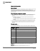
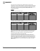
To enable 100K Ω thermistor on input, see the following table for additive values.
SENSOR SEL
Value *
Description
0
Analog Room Unit, 10K
1
Select Digital Room Unit (for temperature sensing and setpoint dial), 10K
2
Relative Humidity (RH) sensing, 10K
3
Digital Room Unit, RH, 10K
4
CO
2
sensing, 10K
5
Digital Room Unit, CO2, 10K
7
Digital Room Unit, RH, CO2, 10K
8
Analog Room Unit, 100K
9
Digital Room Unit, 100K
11
Digital Room Unit, RH, 100K
13
Digital Room Unit, CO2, 100K
15
Digital Room Unit, RH, CO2, 100k
16
(Not used)
Example 1: Digital Room Unit with temperature, RH, CO2 and 10K thermistor.
1+2+4+0 = 7
Example 2: Analog Room unit with 100K thermistor. 0+0+0+8 = 8