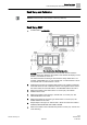
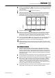
Fume Hood Sash Open Area Module (SOAM) Application 2957: Dual Bench style – Dual Combination with 2 to 4 Horizontal Sashes in the Vertical Carrier Configuration Start-up Procedures Building Technologies A6V10801619 07.06.
Table of Contents Before You Begin ..................................................................................................3 Verifying Power .........................................................................................................3 Installing USB Driver .................................................................................................3 Verifying Slave Mode Application ..............................................................................
Before You Begin Verifying Power Before You Begin WARNING A fume hood is a safety device. Anyone attempting to start up a Fume Hood Controller and its related equipment must have completed Operations Training. WARNING DO NOT connect to the USB port of the SOAM while the fume hood is in operation. At the job site, locate the major control system and the mechanical and electrical drawings. This should include any components working in conjunction with the Sash Open Area Module (SOAM).
Before You Begin Setting Controller Address NOTES: Only WCIS 4.1 or higher is compatible with this device. In order to save configuration values, you must either change WCIS settings (select Write to EEPROM only) or double-click a subpoint to open a dialog box. Setting Controller Address 1. If using the sensor bus to communicate the face area: Verify CTLR ADDRESS is correct (default is 51 and does not need to be changed). Setting the Application 1. Select the desired application.
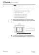
Before You Begin Fume Hood Specific Sash Setup and Calibration Sash Setup and Calibration NOTE: Enter all measurements to the nearest .0.25 inch (0.635 cm). Sash Setup 2957 1. Set REPORT to OVERVIEW. Nine Combination Sash Configuration. NOTES: Numbers on the sashes show how the sash is wired. After the physical sashes are calibrated, the position of the sashes will display in POS SASH 1, POS SASH 2, and so on. The horizontal sash numbering in vertical sash 2 always starts with 7.
Before You Begin Fume Hood Specific Sash Setup and Calibration NOTE: If segment A and segment B dimensions are the same, only setup segment A. – If all the sash panels in both segments are the same width, set PANL WDTH 03 to this value. – If all even horizontal panels are one size and all odd horizontal panels are another size. a. Set PANL WDTH 03 to the width of the odd sashes. b. Set PANL WDTH 04 to the width of the even sashes. – If all panels are different sizes. a.
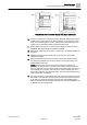
Before You Begin Fume Hood Specific Sash Setup and Calibration Vertical Sash Fume Hood with Bypass Area Open and Closed. 10. If there is no restriction on the bypass, leave BYPASS OPEN at the default (100%). If the bypass area has an airflow restrictor covering the open area, such as a perforated grille or louvers, estimate the open percentage of the bypass area. Set BYPASS OPEN to the appropriate value. 11. Repeat steps 8 through 10 for vertical sash 2.
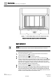
Before You Begin Fume Hood Specific Sash Setup and Calibration Example Combination Sash Fume Hood with Fixed Area. Sash Calibration NOTE: It is recommended that the vertical sash be calibrated before the horizontal sashes. Starting with the first side, side A. 1. Set CAL SASH NUM to 1. It is recommended that the vertical sash be calibrated before the horizontal sashes. 2. Set CAL SASH LOC to MIN for minimum opening. 3. Slide the vertical sash to the closed position.
Before You Begin Fume Hood Specific Sash Setup and Calibration 6. Set CAL SASH NUM back to 0 or to the number of the horizontal sash panel to be calibrated (sashes 3 through 6). This locks to sash calibration into the sash aggregator. 7. Set CAL SASH LOC to MIN for minimum opening. 8. Slide the sash panel to be calibrated to the far left. Measure the distance from the left end of the track to the left edge of the sash panel. Set CAL SASH POS to this value.
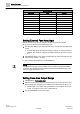
Before You Begin Setting External Face Area Input Sash Point/Wiring. Sash Panel Point Descriptor Vertical 1 31 POS SASH 1 Vertical 2 32 POS SASH 2 Horizontal 3 33 POS SASH 3 Horizontal 4 34 POS SASH 4 Horizontal 5 35 POS SASH 5 Horizontal 6 36 POS SASH 6 Horizontal 7 37 POS SASH 7 Horizontal 8 38 POS SASH 8 Horizontal 9 39 POS SASH 9 Horizontal 10 40 POS SASH 10 Setting External Face Area Input Skip this section if you are only using one SOAM, leave values at default.
Before You Begin Flashing Controller Firmware NOTE: AO DEADBAND can be set from 0 to 100% in 0.4% increments. 0% will give the actual face area all the time. If a sash input signal is unstable, this will cause an unstable reading to be sent to the output which could cause short-term instability or control problems. Increase the values to give a stable output and remove the signal bounce. A 10% deadband is equal to a ± 5% of the face area. AO DEADBAND defaults to 0%.
Issued by Siemens Industry, Inc. Building Technologies Division 1000 Deerfield Pkwy Buffalo Grove IL 60089 +1 847-215-1000 © Siemens Industry, Inc., 2016 Technical specifications and availability subject to change without notice. Document ID: A6V10801619 Edition: 07.06.