
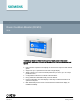
Data Sheet for Product

4
Siemens Industry, Inc.
A6V11402065_en
Smart Infrastructure
2020-07-30
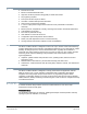
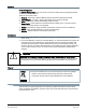
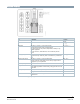
Mounting
Ensure rough-in box is ready to receive the Room Condition Monitor.
a) Reference pressure side.
b) 1-Gang electric box.
c) Room pressure side.
d) Room Condition Monitor (Display hinges down during installation then snaps in place when
mounting is complete).
e) Room Condition Monitor (may be mounted inside or outside room).
f) Wall cavity.
g) Electrical box (3-Gang double-deep if using on-board sensor, single deep if no on-board
sensor).
Installation
WARNING
No internal line protection for supply lines to external consumers
Risk of fire and injury due to short-circuits
● Adapt the line diameters as per local regulations to the rated value of the installed fuse.
Ensure the rough-in box is installed.
See the
RPM Series Room Condition Monitor Installation instructions (A6V11402061)
for details
Commissioning
The Tools (gear icon) will begin the initial setup of the Room Condition Monitor.
The Settings menu includes several functions:
● Device Configuration, which sets all the parameters of home screen and unit functionality.
● Diagnostics, which performs system, network, and I/O tests on the unit.
● Maintenance, which allows pressure sensor calibration, USB cloning, and other software
functions.
● About, which shows the unit model, serial number, calibration date, and other system
information.
See the
RPM Series Room Condition Monitor Start-up (A6V11402069)
for detailed instructions.